Air separator by utilizing cold energy of liquefied natural gas

A technology for the separation of liquefied natural gas and air, applied in the direction of cold treatment separation, liquefaction, refrigeration and liquefaction, etc., can solve the problem of waste of cold energy, and achieve the effects of ensuring equipment safety, compact structure, and reduced power consumption

Inactive Publication Date: 2003-04-02
UNIV OF SCI & TECH OF CHINA
View PDF0 Cites 41 Cited by
  • Summary
  • Abstract
  • Description
  • Claims
  • Application Information

AI Technical Summary

Problems solved by technology

And cold energy is a kind of very precious energy, with seawater heating method, just make the precious cold energy of liquefied natural gas be wasted in vain

Method used


Image

  • Air separator by utilizing cold energy of liquefied natural gas
  • Air separator by utilizing cold energy of liquefied natural gas
  • Air separator by utilizing cold energy of liquefied natural gas

Examples


Embodiment 1

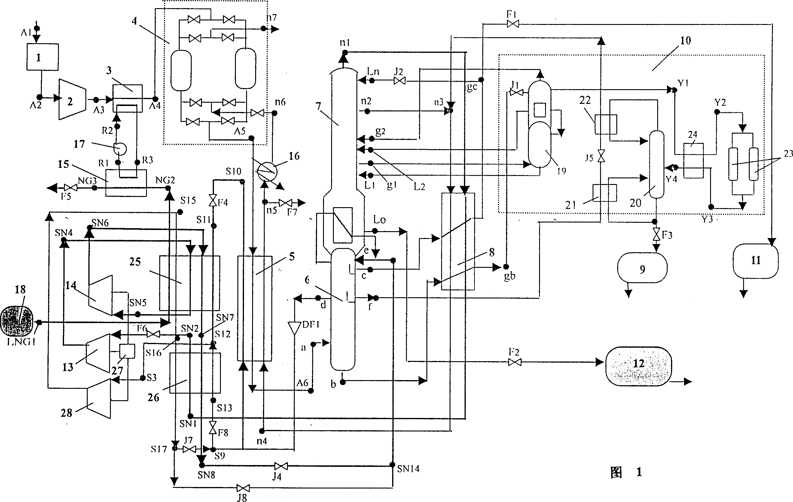
[0019] The equipment that the air separation plant of embodiment 1 adopts and connection route thereof are (seeing as shown in accompanying drawing 1):

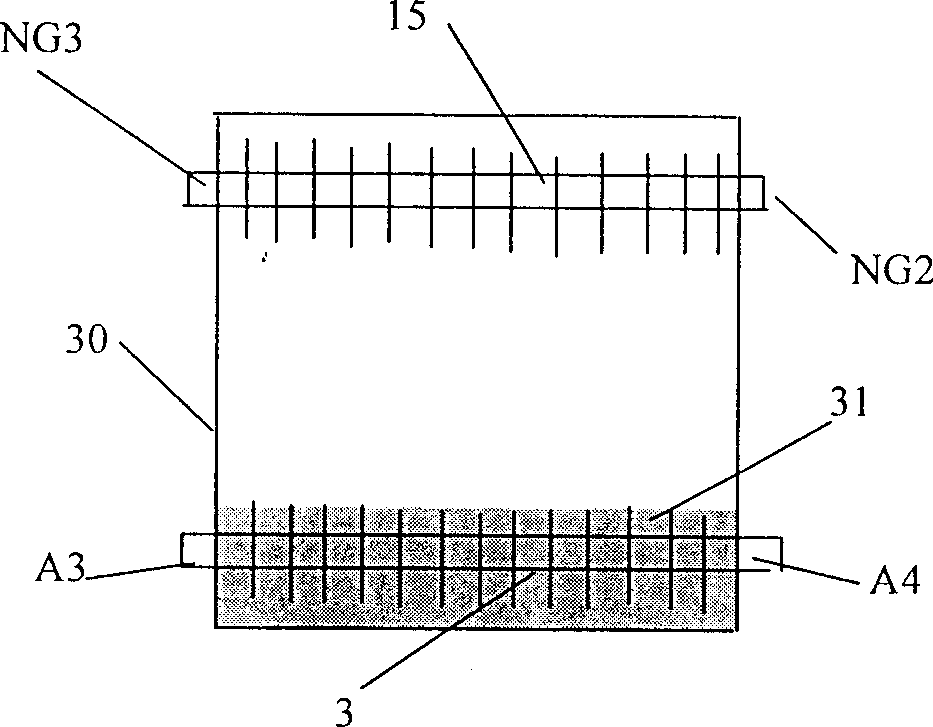
[0020] The air filter 1 has an air inlet A1, and its outlet is connected to the inlet A2 of the air compressor 2; the outlet of the air compressor 2 is connected to the air inlet A of the air cooler 3 3The air outlet of the air cooler 3 is connected to the air inlet of the molecular sieve adsorption system 4, connection point A4; the air outlet of the molecular sieve adsorption system 4 is connected to the inlet of the high-pressure air heat exchange tube at the top of the hot end of the main heat exchanger 5, connection point A5; The outlet A6 of the high-pressure air heat exchange tube of the main heat exchanger 5 is located at the bottom, and it is connected with the high-pressure air inlet a of the high-pressure fractionation tower 6; the liquid air outlet b of the high-pressure fractionation tower 6 is connected to the su...

Embodiment 2

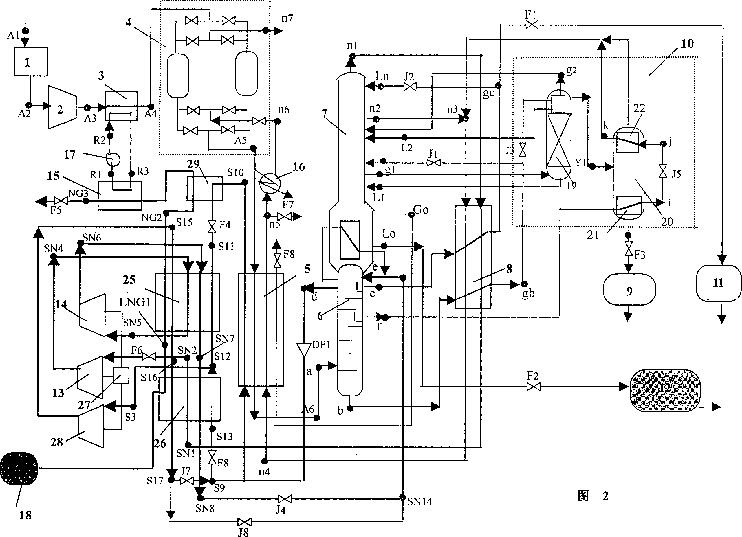
[0041] The air separation plant of embodiment 2 and the different equipment of embodiment 1 and connection route thereof are (seeing accompanying drawing 2 shown):

[0042] A pre-external nitrogen pre-cooler 29 is added on the top of the LNG heat exchanger 25, wherein only two heat exchange passages for liquefied natural gas and circulating nitrogen from the main heat exchanger 5 are provided, and the heat exchange of the liquefied natural gas The inlet of the flow channel is connected to the outlet of the liquefied natural gas heat absorbing pipe LNG1→NG2 of the LNG heat exchanger 25, and the outlet of the liquefied natural gas heat exchange flow channel is connected to the inlet of the natural gas channel of the natural gas reheating heat exchanger 15, and its circulating nitrogen gas exchange The inlet of the hot runner is connected to the outlet S10 of the circulating nitrogen heat recovery channel of the main heat exchanger 5, and its outlet is connected to the regulating ...


PUM


Abstract

An air separator using the cold energy generated by liquefying natural gas to prepare liquefied oxygen, liquefied nitrogen and liquefied argon is based on existing air separator, and features that the multi-stage circulating nitrogen compressors, LNG heat exchanger and circulated nitrogen heat exchanger are additionally used to form a combined refrigerating system, and an air cooling system is also used.

Description

Technical field: [0001] The invention relates to a liquefied natural gas cold energy utilization and an air separation device. Background technique: [0002] The air separation device is a device that uses air as a raw material to produce oxygen, nitrogen, argon and their liquids by liquefying the air and separating it according to the boiling points of oxygen, nitrogen, argon, etc. Liquefied air usually uses the Linde cycle or other improved cycles. In layman's terms: first compress the air to high pressure, use cooling water to cool the compressed air to normal temperature, let the high-pressure air throttling or expand to produce low temperature, and through the heat recovery The heat exchanger cools the high pressure air with the return flow of cold air it generates, so the high pressure air is either throttled at a lower temperature or expanded to a lower temperature, and the cycle continues until the air is liquefied. After the air is liquefied, according to the diffe...

Claims


Application Information

Patent Timeline
Patent Type & Authority Applications(China)
IPC IPC(8): F25J3/00F25J3/02F25J3/04
CPCF25J3/04648F25J2205/60F25J3/0406F25J3/04739F25J3/04351F25J3/04412F25J3/04266F25J2270/904F25J3/04157F25J2210/62F25J3/04224F25J3/04727F25J3/04678
Inventor 陈则韶程文龙
Owner UNIV OF SCI & TECH OF CHINA
Why Eureka
Try Eureka