Protective gas on-line purging copper tube bright continuous annealing furnace

A technology of protective gas and continuous annealing furnace, which is applied in the direction of furnace, furnace type, lighting and heating equipment, etc., and can solve problems such as low efficiency, high price and deformation

Inactive Publication Date: 2003-06-25
张民苏 +2
View PDF0 Cites 24 Cited by
  • Summary
  • Abstract
  • Description
  • Claims
  • Application Information

AI Technical Summary

Problems solved by technology

One of the existing bright annealing furnaces for copper tubes is a (vertical or horizontal) movable furnace with a seal. Then put the furnace into the heating furnace for heating, and then place the heated furnace outside for cooling treatment. After the room temperature is cooled, the furnace door is sealed and the copper tube is taken out. This kind of annealing furnace is The overall heating transfer heat and heating the copper tube consumes a lot of power, and at the same time, the cooling time is long, the charging material is small, and continuous production is not possible, so the efficiency is low; Continuous bright annealing furnace with vacuum air lock chamber. The feeding area and the discharging area of ​​this kind of annealing furnace are two vacuum air lock chambers. , and then filled with protective gas, and separated by two furnace doors in the heating zone and cooling chamber to prevent the oxidation of copper tubes during the heating and cooling process
The sealing of the above-mentioned annealing furnace is very difficult, especially the front and rear two-stage furnace doors of the heating zone of the continuous annealing furnace manufactured abroad. The furnace door often opens and closes automatically under the condition of high temperature and airtightness in the furnace. The installation, production and maintenance of the sealed pressure mechanism are relatively difficult. At present, there is no self-made continuous bright annealing furnace with a vacuum lock chamber in China; the existing domestic bright annealing furnace with a furnace door is installed outside the furnace. The outer end of the feeding place adopts ...

Method used


Image

  • Protective gas on-line purging copper tube bright continuous annealing furnace
  • Protective gas on-line purging copper tube bright continuous annealing furnace
  • Protective gas on-line purging copper tube bright continuous annealing furnace

Examples


Embodiment Construction

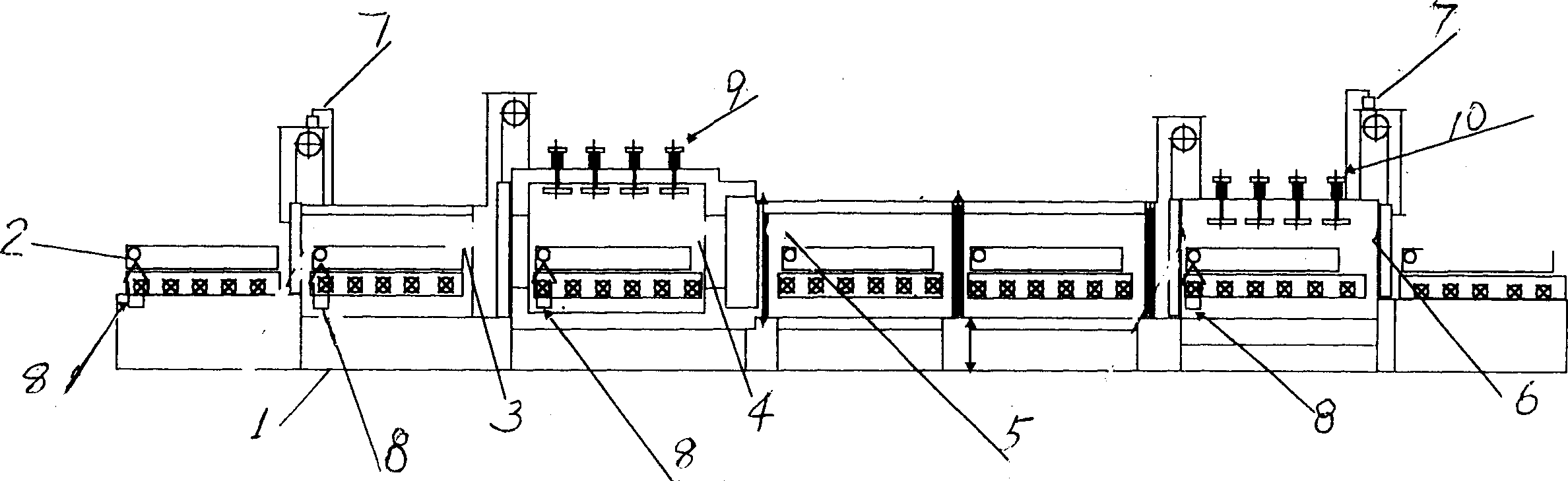
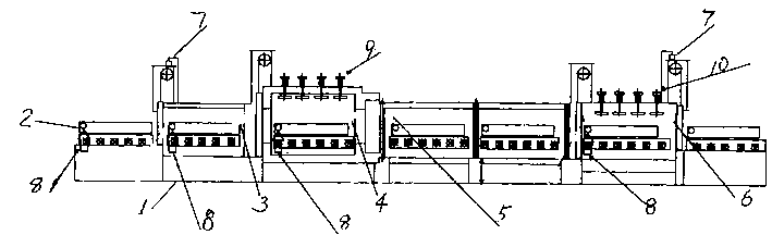
[0011] The present invention will be further described below in conjunction with the accompanying drawings and embodiments.

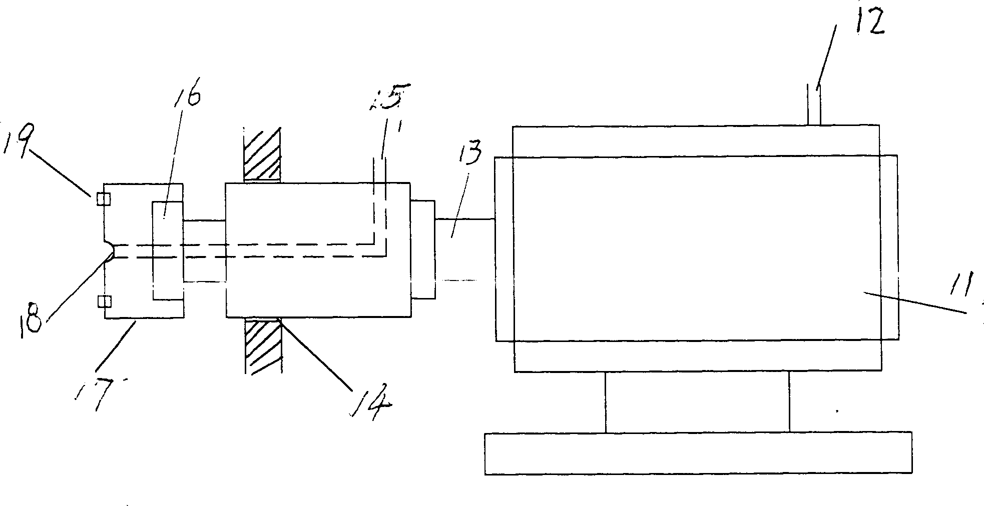
[0012] The present invention comprises furnace body 1, and this furnace body mainly comprises material rack 2, front chamber 3, heating chamber 4, water cooling chamber 5, forced cooling chamber 6 in turn, and it is different from prior art in that: material rack 2 is provided with air inlet pipe and The air outlet pipe is installed on both sides of the outer wall of the front chamber, the heating chamber, the water cooling chamber and the forced cooling chamber, and the copper pipe internal purging device 8 and the copper pipe internal exhaust device are installed, and the copper pipe internal purging device and the copper pipe internal exhaust device The structure is the same, except that the air inlet of the purging device in the copper pipe is the exhaust port of the exhaust device in the copper pipe, and the air inlet pipes in the air purging device...


PUM


Abstract

The continuous copper tube bright annealing furnace features that there are air intake pipe and air exhaust pipe in the material rack; copper tube inner purging unit and inner air exhaust unit in the front chamber, heating chamber, water cooling chamber and forcing cooling chamber; that all the air intake pipes are communicated and so do the air exhaust pipes. The present invention may be used to produce bright copper tube with inner surface of superhigh cleanness. The annealing furnace also has the features of low manufacture cost, low air consumption, low power consumption, high production efficiency and continuous production.

Description

Technical field: [0001] The invention relates to annealing process equipment for nonferrous metal materials, in particular to a bright continuous annealing furnace with protective gas on-line purging copper tubes. Background technique: [0002] As we all know, in order to obtain different mechanical properties (soft state and semi-hard state) and have brighter inner and outer surfaces, copper tubes need to be annealed at different temperatures in an annealing furnace in a protective atmosphere or in a vacuum state. One of the existing bright annealing furnaces for copper tubes is a (vertical or horizontal) movable furnace with a seal. Then put the furnace into the heating furnace for heating, and then place the heated furnace outside for cooling treatment. After the room temperature is cooled, the furnace door is sealed and the copper tube is taken out. This kind of annealing furnace is The overall heating transfer heat and heating the copper tube consumes a lot of power, a...

Claims


Application Information

Patent Timeline
IPC IPC(8): C22F1/08F27B9/04
Inventor 张民苏蒋明根严加伦
Owner 张民苏
Why Eureka
Try Eureka