RAM high speed test control circuit and its testing method

A test method and test control technology, applied in the direction of semiconductor/solid-state device test/measurement, electronic circuit test, instrument, etc., can solve the problem of inconvenient maintenance, fault location, RAM fault type information statistical analysis, test speed can not meet the speed requirements, RAM The fault location is not detailed, and the maintenance and fault type statistics are convenient, the cost of test equipment is low, and the test is flexible.

Inactive Publication Date: 2003-07-02
HUAWEI TECH CO LTD
View PDF0 Cites 35 Cited by
  • Summary
  • Abstract
  • Description
  • Claims
  • Application Information

AI Technical Summary

Problems solved by technology

The capacity of the current memory is getting larger and larger. If the test is completed by software, the test time will be very long. When testing RAM in production or testing RAM in some products, the test speed cannot m

Method used


Image

  • RAM high speed test control circuit and its testing method
  • RAM high speed test control circuit and its testing method
  • RAM high speed test control circuit and its testing method

Examples


Embodiment Construction

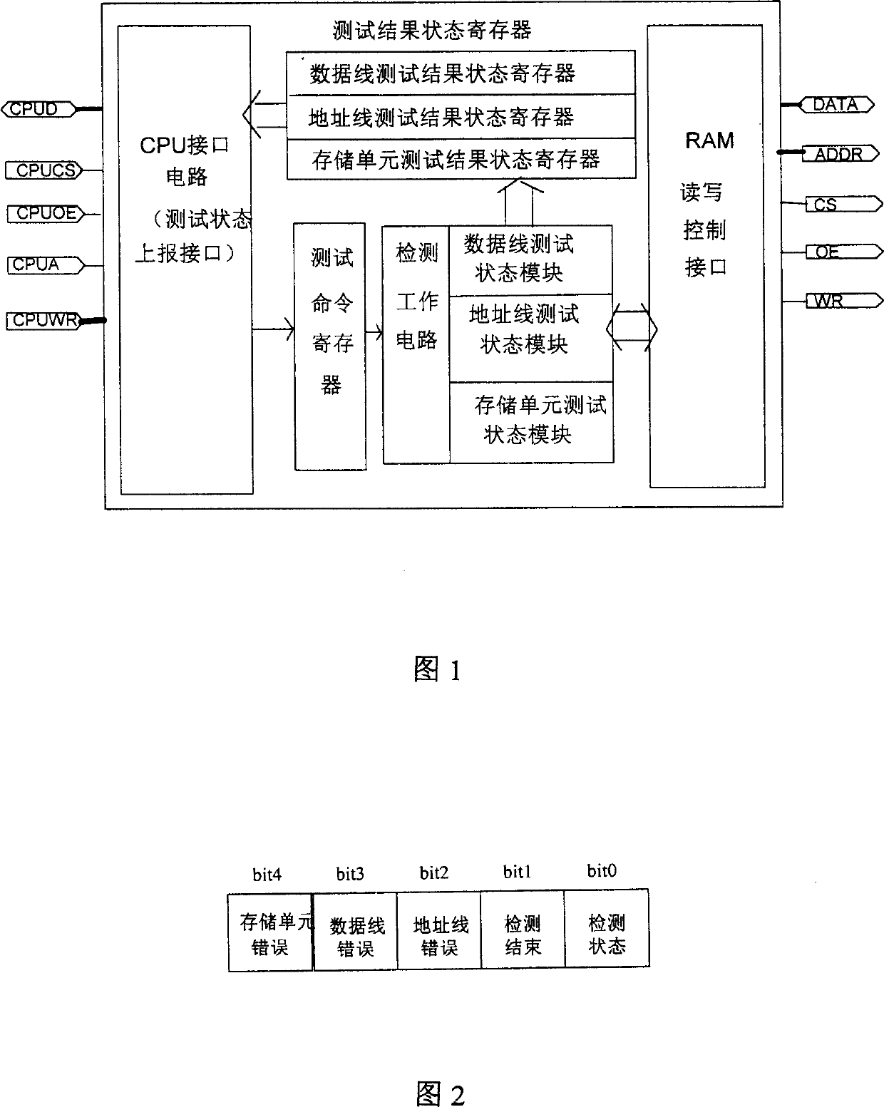
[0029] The diagnostic process of the data memory RAM is to check the effectiveness of each memory cell to perform read / write operations. The test of the memory includes three basic aspects: one is the test of the data line, the other is the test of the address line and the decoding, and the third is the test of the storage unit; the detection of the RAM is to pass a certain test pattern to test the memory unit and address decoding circuit functions for quick and efficient checks. The test of the storage unit can cover the errors of the data line test and the address line test. The purpose of adding a separate data line and address line test is to locate the fault of the detailed data line address line test.

[0030] The RAM detection control circuit of the present invention is shown in FIG. 1 . The circuit includes: a CPU interface circuit, a RAM read-write control interface, a test command register, a test result status register and a test working circuit. Each part is furt...


PUM


Abstract

A control circuit for high-speed test of RAM is disclosed, which is based on hardware logic for correct location of failure and high test efficiency. Its test method includes such steps as setting up the state of test command register, choosing test type, strobing test register, testing data lines by comparison, testing address lines by comparison, step test of memory units, and analyzing error type by reading state registers.

Description

technical field [0001] The invention relates to memory detection technology, in particular to a high-speed RAM (random access memory) test method and a test control circuit realized by hardware logic. Background technique [0002] In communication products and computer application systems, random access memory (RAM) is the core unit used to store raw data, intermediate processing results and other information. It is very important to ensure the normal and reliable operation of the entire system whether the memory can realize normal read / write operations, and no data disparity occurs during the storage / retrieval process. For this reason, it is necessary to conduct a comprehensive test and diagnosis of the memory before the product leaves the factory and the system starts to work. [0003] With the development of communication and computer software and hardware technology, the system requires more and more memory capacity. At the same time, with the rapid development of semi...

Claims


Application Information

Patent Timeline
IPC IPC(8): G01R31/28G11C29/00H01L21/66
Inventor 王洪英
Owner HUAWEI TECH CO LTD
Why Eureka
Try Eureka