
Technological method and equipment for preparing nitrogen trifluoride gas

A process method, nitrogen trifluoride technology, applied in the direction of electrolysis components, electrolysis process, etc., can solve the problems of affecting the continuous operation of production, prone to explosion, complicated operation, etc., to eliminate unsafe hidden dangers, equipment operation safety, and easy operation. Effect

Inactive Publication Date: 2003-10-22
PERIC SPECIAL GASES CO LTD
View PDF1 Cites 25 Cited by
  • Summary
  • Abstract
  • Description
  • Claims
  • Application Information

AI Technical Summary

Problems solved by technology

[0004] In general, the chemical synthesis method has the characteristics that the synthesis reaction is relatively safe, and its disadvantage is that the NF in the product after the synthesis reaction 3 The content of gas is lower than that of electrolysis, and its CF 4 The content is generally very high (above 0.3%); while using NH 4 F-xHF (or add a small amount of KF) is NF prepared by electrolysis of electrolyte system 3 The gas has a higher yield and purity, which is more conducive to purification and preparation of high-purity NF 3 Gas, its disadvantage is that it is prone to explosion during the electrolysis process
[0005] Usually, in NH 4 F-xHF (or add a small amount of KF) is the electrolytic preparation of NF in the electrolyte system 3 The gas uses carbon as the anode. The carbon material anode has the advantages of long service life and less electrolytic waste residue, but it also has a serious disadvantage: the NF produced by electrolysis 3 CF in gas 4 High content (generally higher than 500ppm)
[0007] To remove NH in the anode electrolysis gas 4 F and HF and other high-boiling impurities, the traditional method is to absorb with solid alkali or wash with lye, these two methods require frequent replacement of reagents, which affects the continuous operation of production, and the operation is more cumbersome

Method used


Image

  • Technological method and equipment for preparing nitrogen trifluoride gas
  • Technological method and equipment for preparing nitrogen trifluoride gas

Examples


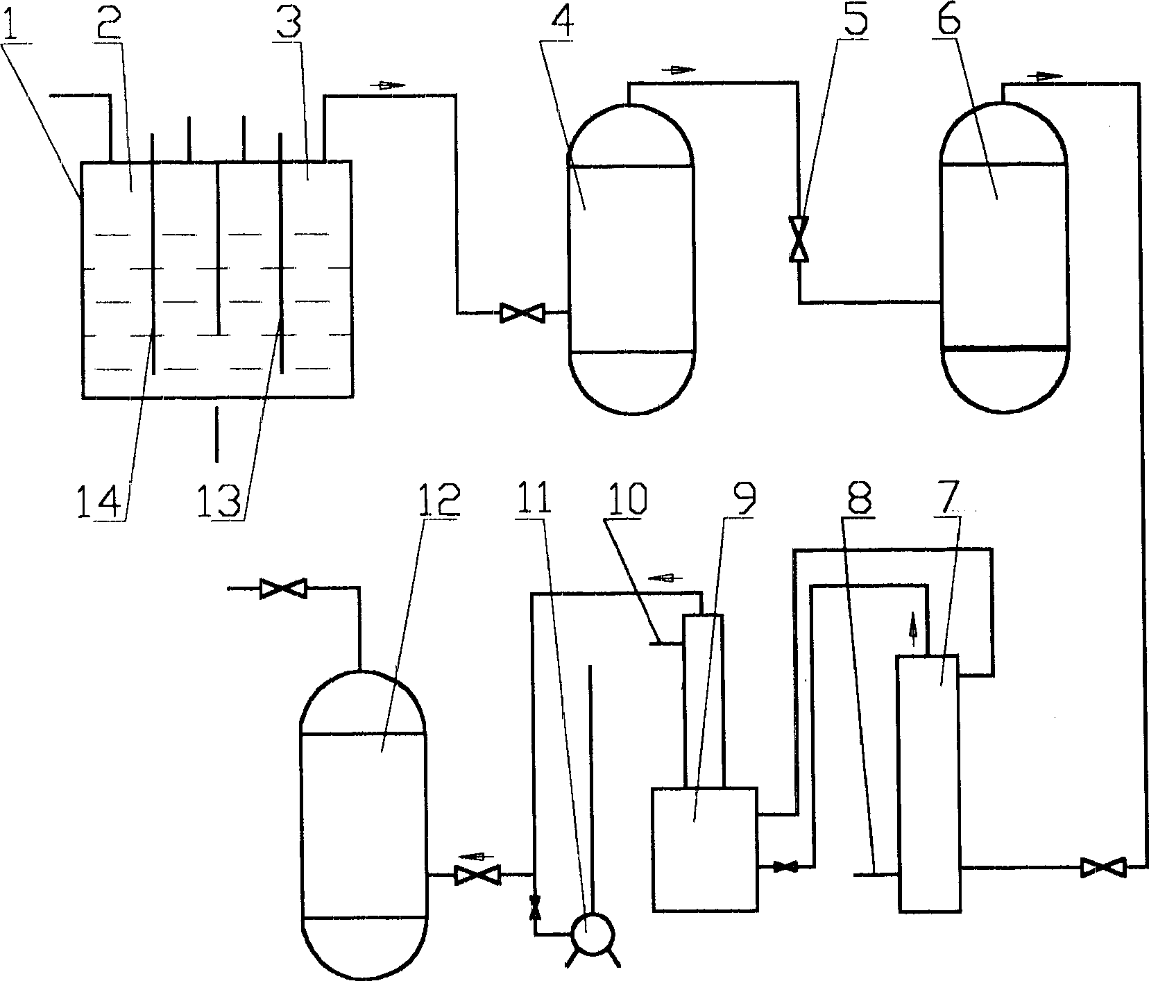
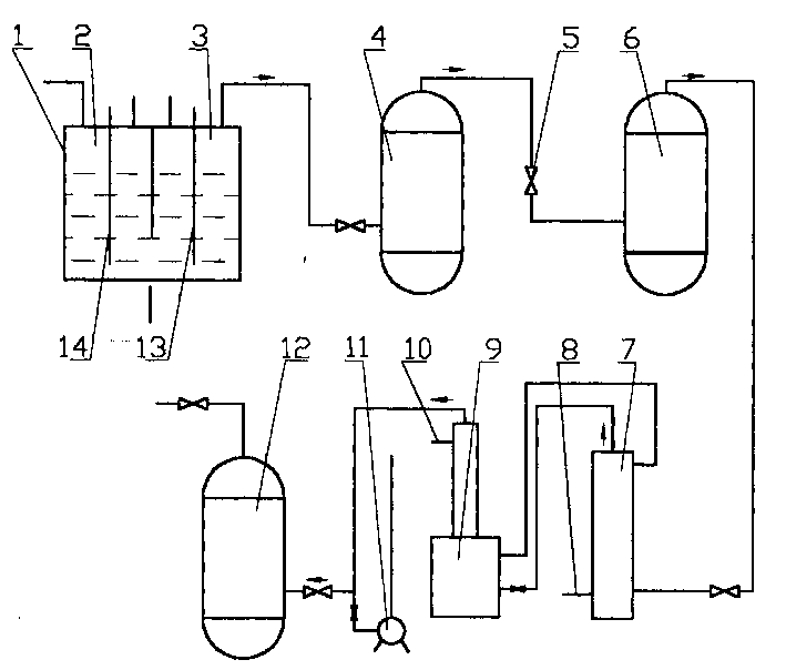
Embodiment Construction

[0028] The present invention will be described in more detail below with reference to the process flow diagram of the present invention. The present invention can have many specific implementations, and is not limited to the specific implementations described herein.

[0029] The equipment of the present invention comprises an electrolytic cell 1, a pressure balance tank 4, a low pressure tank 6, a low-temperature cooling tower 7, an ultra-low temperature cold trap 9, a vacuum pump 11, and crude product NF 3 The gas storage tank 12, the anode area of ​​the electrolytic cell 1 are in sealing communication with the pressure balance tank 4 through the pipeline, the pressure balance tank 4 is in sealing communication with the low-pressure tank 6 through the pipeline and the regulating valve 5, and the low-pressure tank 6 is in sealing communication with the low-temperature cooling tower 7 through the pipeline , the low-temperature cooling tower 7 is in sealed communication with th...


PUM


Abstract

The present invention relates to a process for preparing NF3 gas and its equipment. It is characterized by that the anodic electrolytic gas in the electrolytic cell is fed into a pressure balancing tank by means of pipe, then fed into a low pressure tank via regulating valve, and said gas is fed into a low-temp. cooling tower by means of pipe to remove high-boiling point impurities of NH4F and HFfrom said anodic electrolytic gas to obtain NF3 gas, then the NF3 gas is fed into an ultralow temp. cold trap to make liquification and collection, and remove low-boiling point impurities or N2 and O2 from it by adopting the measure of evacuating cold trap, after the NF3 gas is collected and liquified in the ultralow-temp. cold trap, heating the cold trap and distilling said NF3 gas and pressing it into crude NF3 gas storage tank, the material of anode in the electrolytic cell is high-purity nickel.

Description

(1) Technical field [0001] The invention relates to a process and equipment for preparing nitrogen trifluoride gas, which is suitable for 4 F-xHF (or add a small amount of KF) for the electrolysis of the electrolyte system to prepare NF 3 gas, this crude NF 3 The gas can be directly used to prepare high-purity NF 3 gas. (two), background technology [0002] NF 3 Gases are widely used in fields such as high-energy lasers, semiconductor technology, and chemical vapor deposition, and have good application prospects. But as an electron gas, it is NF 3 The purity of the gas has higher requirements, generally its purity should not be lower than 99.99%, and the key impurities such as CF 4 The content should not be higher than 50ppm, which makes the preparation of high-purity NF 3 Gas is more difficult. [0003] Prepare NF 3 The method of gas can basically be divided into chemical synthesis method and electrolysis method, and they all have many ways to realize it. The more ...

Claims


Application Information

Patent Timeline
IPC IPC(8): C25B1/24
Inventor 李本东高世选
Owner PERIC SPECIAL GASES CO LTD
Learn More