Deep well detection optical-fiber transmission system

A technology for detecting optical fiber and transmission system, which is applied in the direction of measurement, wellbore/well components, fiber mechanical structure, etc. It can solve the problems of non-use, etc., and achieve the effect of improving the accuracy of information transmission, improving logging efficiency, and reducing loss

Inactive Publication Date: 2003-12-10
SHANGHAI LIGHT GUIDE TRANSMISSION TECH INST
View PDF1 Cites 8 Cited by
  • Summary
  • Abstract
  • Description
  • Claims
  • Application Information

AI Technical Summary

Problems solved by technology

The information that can be transmitted by one optical fiber can be said to be infinite in terms of the amount of logging information at present, but in various optical fiber transmission systems, all kinds of optical transceivers are in the environment of normal temperature and pressure, and relatively low temperature The use of the same photoelectric hybrid cable is also used in the environment of normal temperature and pressure or more than 10 Mpa. There are no examples and related product reports that are used in high temperature (above 150°C) and high pressure (above 60Mpa) environments at the same time.

Method used


Image

  • Deep well detection optical-fiber transmission system
  • Deep well detection optical-fiber transmission system
  • Deep well detection optical-fiber transmission system

Examples


Embodiment Construction

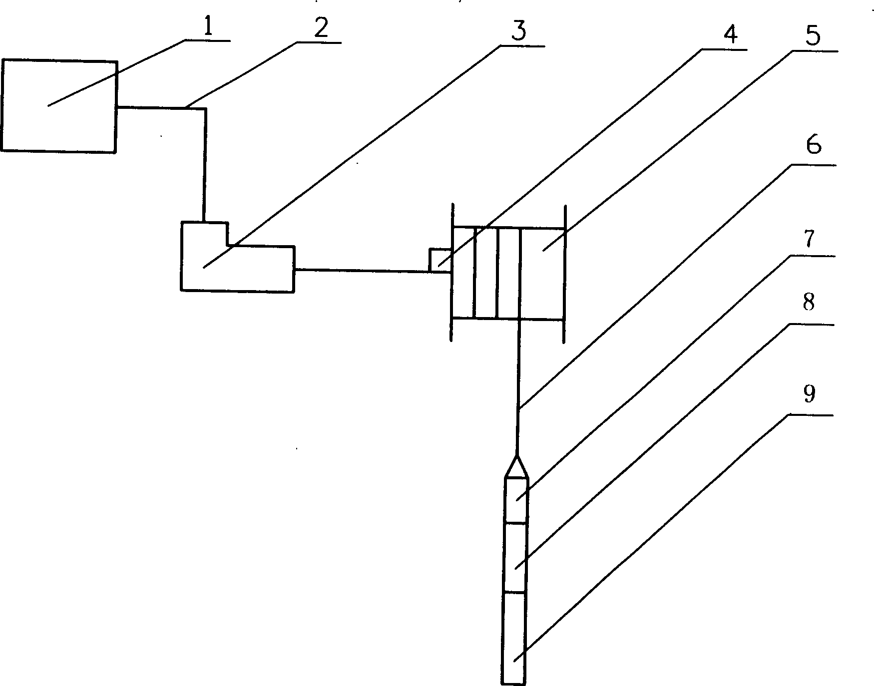
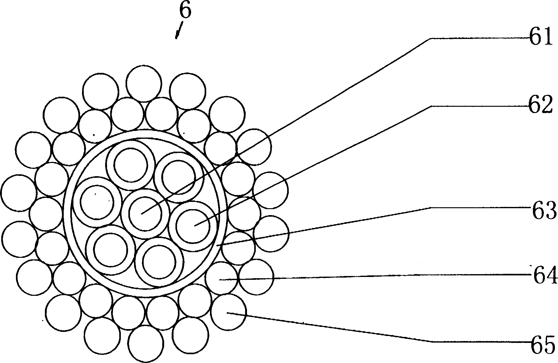
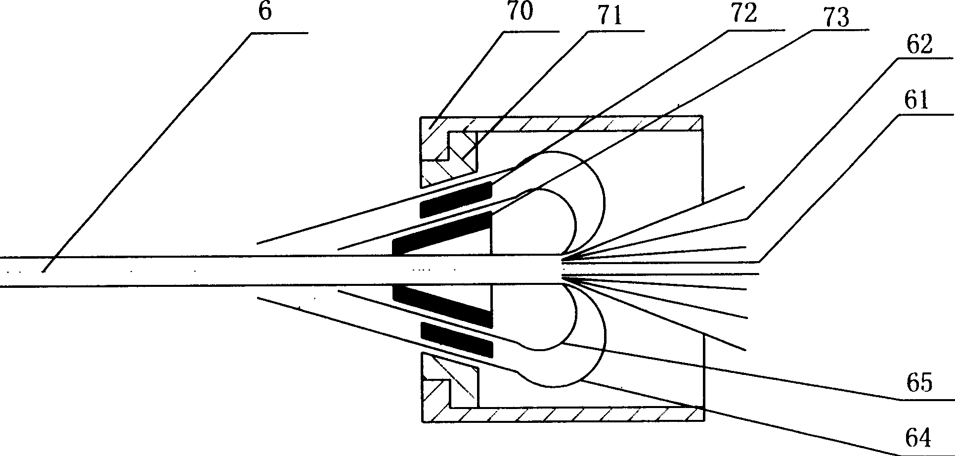
[0033] see first figure 1 ,Depend on figure 1 It can be seen that the optical fiber transmission system for deep well detection of the present invention includes ground instruments 1, cables 2, rotary joints 3, drawworks 5, and downhole instruments 9, and is characterized in that there are also ground optical transceivers 4, photoelectric hybrid cables 6, and downhole photoelectric hybrid cable connectors 7. And the downhole optical transceiver 8, the ground instrument 1 is connected with the ground optical transceiver 4 through the cable 2 and the rotary joint 3, the photoelectric hybrid cable 6 is wound on the winch 5, the ground end of the photoelectric hybrid cable 6 is connected to the surface optical transceiver 4, and the downhole end The downhole optical transceiver 8 and the downhole instrument 9 are connected through the downhole photoelectric hybrid cable connector 7. The downhole optical transceiver 8 is covered with a heat-resistant protective cover 81 and a press...


PUM


Abstract

The deep-well detection optical fibre transmission system includes surface instrument, cable, swivel, hoisting winch and downhole instrument. It also has surface optical terminal machine, electro-optic mixed cable, downhole electro-optic mixed cable coupling device and downhole optical terminal machine, the surface instrument is connected with surface optical terminal machine by means of cable and swivel, the electro-optic mixed cable is winded round hoisting winch, said electro-optical mixed cable ground surface end is connected with surface optical terminal machine, and its downhole end is connected with downhole optical terminal machine and downhole instrument by means of downhole electro-optical mixed cable coupling device.

Description

Technical field: [0001] The invention relates to deep well detection and photoelectric transmission, in particular to a deep well detection optical fiber transmission system which applies the optical fiber transmission technology to oil field logging operations. Background technique: [0002] In the oilfield logging operation, in order to transmit the information detected by the detector deep in the downhole from the downhole to the surface for processing. At present, cable transmission technology is used to complete, and there is no instance report of applying optical fiber transmission technology. In order to find out the geological conditions of the inner wall of the oil well and its vicinity, such as rock type, structure, porosity, oil, water, or gas and its distribution, temperature, pressure and flow velocity, etc. related to oil and gas production, etc. For detailed information, it is necessary to lower dozens of detection instruments into the oil well to measure dif...

Claims


Application Information

Patent Timeline
Patent Type & Authority Applications(China)
IPC IPC(8): E21B47/135G02B6/44
Inventor 吴任龚锡康
Owner SHANGHAI LIGHT GUIDE TRANSMISSION TECH INST
Why Eureka
Try Eureka