Optical fibre lateral edge coupling method of pumping light source

A pump light source, fiber coupling technology, applied in the coupling of optical waveguides, optics, light guides, etc., can solve the problem of difficult to obtain coupling efficiency, and achieve high conversion efficiency, easy implementation, and improved conversion efficiency.

Inactive Publication Date: 2003-12-10
WUHAN RAYCUS FIBER LASER TECHNOLOGY CO LTD
View PDF2 Cites 25 Cited by
  • Summary
  • Abstract
  • Description
  • Claims
  • Application Information

AI Technical Summary

Problems solved by technology

[0004] Grudimin.A.B. et al. (International Patent, WO 00 / 67350) invented the edge coupling method in which the pump fiber and the DC fiber are in contact with each other. The principle is as follows figure 2 As shown, it is difficult to obtain high coupling efficiency because the pump fiber is not drawn

Method used


Image

  • Optical fibre lateral edge coupling method of pumping light source
  • Optical fibre lateral edge coupling method of pumping light source
  • Optical fibre lateral edge coupling method of pumping light source

Examples


Embodiment 1

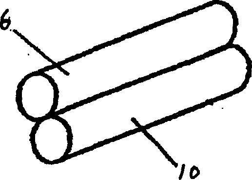
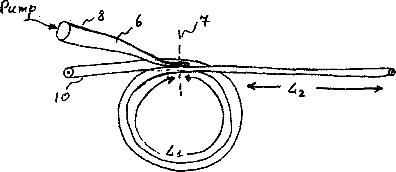
[0032] image 3 It shows a side coupling method of the present invention, the DC fiber 10 removes the protection layer in the coupling region 7, and the MM fiber 6 is a multimode fiber, the protection layer is removed in the coupling region 7 and gradually thinned. The DC optical fiber includes a coiled portion with a length of L1 and the remaining portion with a length of L2, and the total length is L1+L2. Therefore, in the coupling area 7, there are 3 cross-sections of the optical fiber, such as Figure 4 , 5 As shown, the sections of the DC fiber can be in optical contact with each other (eg Figure 4 ), or do not touch each other (such as Figure 5 ), the two sections of the DC fiber and the gradually thinned section of the pump fiber are optically in contact with each other, and the optical mutual contact refers to the transfer of the pump light source from the MM fiber end 8 to the DC fiber through fusion or mutual contact .

Embodiment 2

[0034] Figure 6 It shows a schematic diagram of another embodiment of the fiber side coupling method of the pump light source of the present invention. The difference from Embodiment 1 is that in Embodiment 1, when the MM optical fiber 6 and the DC optical fiber 10 reach the optimum in the coupling region 7 After optical contact, only the left input remains and the right input is removed. In this embodiment, the pump light source is introduced from the end 8 of the MM fiber on the left, is converted to the DC fiber in the coupling region 7 and is transmitted clockwise along the DC fiber, and another pump light source is introduced from the end 9 of the MM fiber on the right. Introduced, it is converted to the DC fiber in the coupling region 7 and trans-transmitted counterclockwise along the DC fiber to form bidirectional pumping. This coupling method can further improve the pumping efficiency of the DC fiber.

Embodiment 3

[0036] Figure 7 , 8. 9 shows the third embodiment of the present invention. In Embodiment 1 and Embodiment 2, the DC fiber is only wound into 2 circles, so only 2 sections are fused with a narrowed section of the MM fiber. In this embodiment, the DC fiber can be wound into 3 circles, 4 circles, 7 circles, etc., so that in the coupling region 7, the sections of multiple DC fibers are fused with the section of one MM fiber. The length of each turn of the DC fiber can be equal or unequal, so the distribution of pump light energy coupled to the entire DC fiber can be controlled along the DC fiber. In this embodiment, the MM fiber may or may not be attenuated due to the use of multiple coils of DC fiber.


PUM


Abstract

The present invention relates to an optical fibre side edge coupling method for pumping light source, and includes the following steps: using MM optical fibre as pump input optical fibre, DC optical fibre as one fo producing amplifier or laser, removing protecting layer in the MM optical fibre and DC optical fibre coupled zone and coiling the coupled part of DC optical fibre. The coupling of the above-mentioned two optical fibres adopts chemical contact, i.e. they are mutually molten or mutually combined together. Said invention not only raises the coupling efficiency, but also can make DC optical fibre obtain uniformly pumping and can raise the conversion efficiency from pumping light source to optical fibre laser output.

Description

technical field [0001] The present invention relates to a kind of optical fiber side coupling method applicable to optical fiber amplifiers and optical fiber lasers with uniform segmental pumping, which can effectively convert the light source of multimode semiconductor lasers from any Coupled to DC fiber on the line segment (not terminal), used to manufacture high power output, high conversion efficiency fiber amplifier and fiber laser. Its application fields include optical fiber communication network, processing and processing of metal and non-metal materials, laser engraving, laser marking, laser welding, weld seam processing, precision drilling, laser detection and measurement, laser radar system, laser free space communication, Sensing technology and laser medicine, etc. Its output wavelength ranges from 0.8nm to over 2000nm, and the output continuous optical power ranges from hundreds of milliwatts to thousands of watts. Background technique [0002] In fiber amplif...

Claims


Application Information

Patent Timeline
Patent Type & Authority Applications(China)
IPC IPC(8): G02B6/00G02B6/26H01S3/091
Inventor 阎长鹍
Owner WUHAN RAYCUS FIBER LASER TECHNOLOGY CO LTD
Why Eureka
Try Eureka