Soft base station system based on fiber optic stretch and synchronous method thereof

A technology of optical fiber remote and soft base station, which is applied in the direction of optical fiber transmission, transmission system, optical fiber radio, etc., and can solve the problems of noise sensitivity and the limitation of optical fiber remote distance, etc.

Inactive Publication Date: 2003-12-31
HUAWEI TECH CO LTD
View PDF0 Cites 47 Cited by
  • Summary
  • Abstract
  • Description
  • Claims
  • Application Information

AI Technical Summary

Problems solved by technology

[0047] Aiming at the shortcomings of the repeater in the current signal coverage technology, the purpose of the present invention is to propose a soft base station system and its synchronization method based on optical fiber remote, which transmits the signal of a large-capacity base station to the soft base station through optical fiber. The base sta

Method used


Image

  • Soft base station system based on fiber optic stretch and synchronous method thereof
  • Soft base station system based on fiber optic stretch and synchronous method thereof
  • Soft base station system based on fiber optic stretch and synchronous method thereof

Examples


Embodiment 1

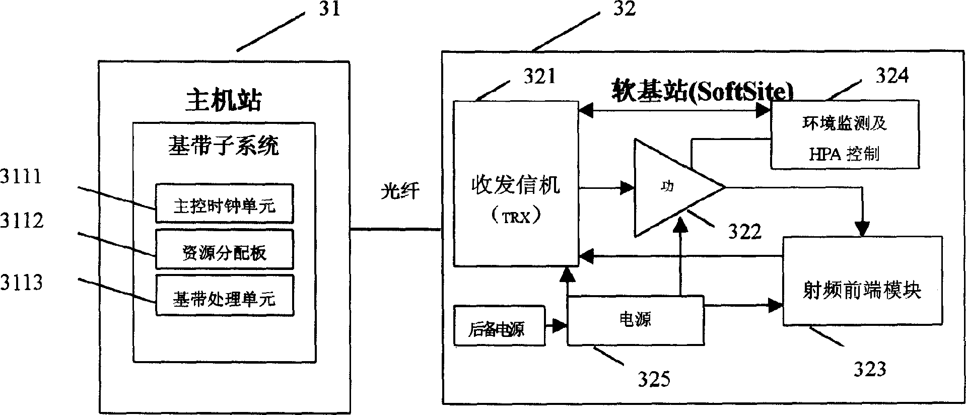
[0083] Such as image 3 Shown is a block diagram of the soft base station system. The soft base station system includes a main base station (ie, a large-capacity base station) 31 and a soft base station 32. The main base station 31 includes a baseband subsystem 311, and the baseband subsystem 311 further includes a main base station. Clock control unit 3111, resource allocation board 3112 and baseband processing unit 3113. The soft base station 32 and the main base station 31 share the main control clock unit 3111 and the baseband processing unit 3113 , and the resource distribution board 3112 is connected to the transceiver 321 of the soft base station 32 through an optical fiber. The soft base station 32 includes a transceiver (ie TRX module) 321 , a power amplifier module 322 , a radio frequency front-end module 323 , an environment and HPA monitoring module 324 and a power supply module 325 .

[0084] The soft base station system of this embodiment includes a large-capaci...

Embodiment 2

[0104] Such as Figure 11 Shown is the TRX cascading networking mode. The soft base station system includes a large-capacity base station and 6 soft base stations, each soft base station is connected by optical fiber level, and the soft base station at the first or last position is connected to the baseband processing module of the large-capacity base station through an optical fiber , Compared with the TRX star network, this networking method can save a lot of optical fibers.

[0105] The structural block diagram of the soft base station is the same as that in Embodiment 1.

[0106] For different TRXs on the same optical fiber, because TRX has no address recognition capability, TRX itself does not know its position in the chain. In this embodiment, the dynamic time slot transmission of data is realized by "bubbling", such as Figure 12 As shown, the baseband processing module of the large-capacity base station loads the configuration management data of each TRX onto the opt...


PUM


Abstract

The invention discloses a soft base station system and process of synchronizing based on optical fiber zooming out. Presently, direct sending stations are used to expand the signal coverage in the mobile communication network, but noise level and low sensitivity are also brought in. The soft base station system based on optical fiber will transform the radio frequency signal directly coupled from the large capacity base station into optical signal through analog optical modulation, which will be transmitted to the soft base station via. the optical fiber, the soft base station will transform the optical signal into the electrical signal, which will radiate to the needed coverage via the service antenna. Apart from all the advantages resulted from using digital transmission and receiving machine, the soft base station has bee proved to increase system capacity, improve the network quality and reduce the occurrence of disconnection.

Description

technical field [0001] The invention relates to a signal coverage technology in a mobile communication network, in particular to a soft base station system and a synchronization method based on optical fiber remote. Background technique [0002] At present, in terms of signal coverage, mobile communication networks still have coverage blind spots or shadow areas, as well as areas with low user density (such as remote mountainous areas), along highways, conference centers, tunnels, tourist areas, etc. Regional business coverage issues. In order to solve the above problems, in addition to adding base stations, it is also a more economical and effective means to use repeaters to expand the coverage of network signals. The repeater can relay, amplify and forward the received signals from the mobile station and the base station. It is a low-cost, simple-to-install device with the function of a small base station. [0003] According to the link m...

Claims


Application Information

Patent Timeline
IPC IPC(8): H04W16/24H04B10/2575H04B10/272H04J13/02H04W88/08
Inventor 葛锦春鲜志成鲁敬农易小卫张琰周旭东周健
Owner HUAWEI TECH CO LTD
Why Eureka
Try Eureka