
Dimethyl ether engine efficient, ultra-low emission combustion system

A technology for combustion systems and engines, applied in engine components, combustion engines, machines/engines, etc., to solve problems such as being unsuitable for practical motor vehicle applications, high nitrogen oxide emissions, and inoperable engines

Inactive Publication Date: 2004-01-28
SHANGHAI JIAO TONG UNIV
View PDF0 Cites 8 Cited by
  • Summary
  • Abstract
  • Description
  • Claims
  • Application Information

AI Technical Summary

Problems solved by technology

Through the retrieval of existing technology, find document: "Engine Performance and Exhaust Characteristics ofDirect-injection Diesel Engine Operated with DME", SAE972973, S.Kajitani, Ibaraki University (engine performance when direct-injection diesel engine burns dimethyl ether and emission characteristics, American Society of Automotive Engineers paper, number: SAE Paper 972973), this paper introduces the combustion system and fuel injection system of the original engine when the direct injection diesel engine uses dimethyl ether as fuel, and the fuel injection system is mainly made by Bosch Type plunger type fuel injection pump and 4-hole fuel injection nozzle; because dimethyl ether has a low boiling point and is easy to vaporize, it will cause air resistance in the fuel injection system and make the engine unable to run normally. pressurization to ensure that the dimethyl ether fuel in the fuel injection system is liquid, this method is not suitable for the application of actual motor vehicles
In addition, the in-cylinder spray combustion method adopted by this technology has nitrogen oxides (NO X ) high emissions, equivalent to the level of the original diesel engine, so it is necessary to take effective measures to further reduce the NOX emissions of dimethyl ether engines, so that the emission performance of dimethyl ether engines can meet the increasingly stringent emission regulations

Method used


Image

  • Dimethyl ether engine efficient, ultra-low emission combustion system
  • Dimethyl ether engine efficient, ultra-low emission combustion system

Examples


Embodiment Construction

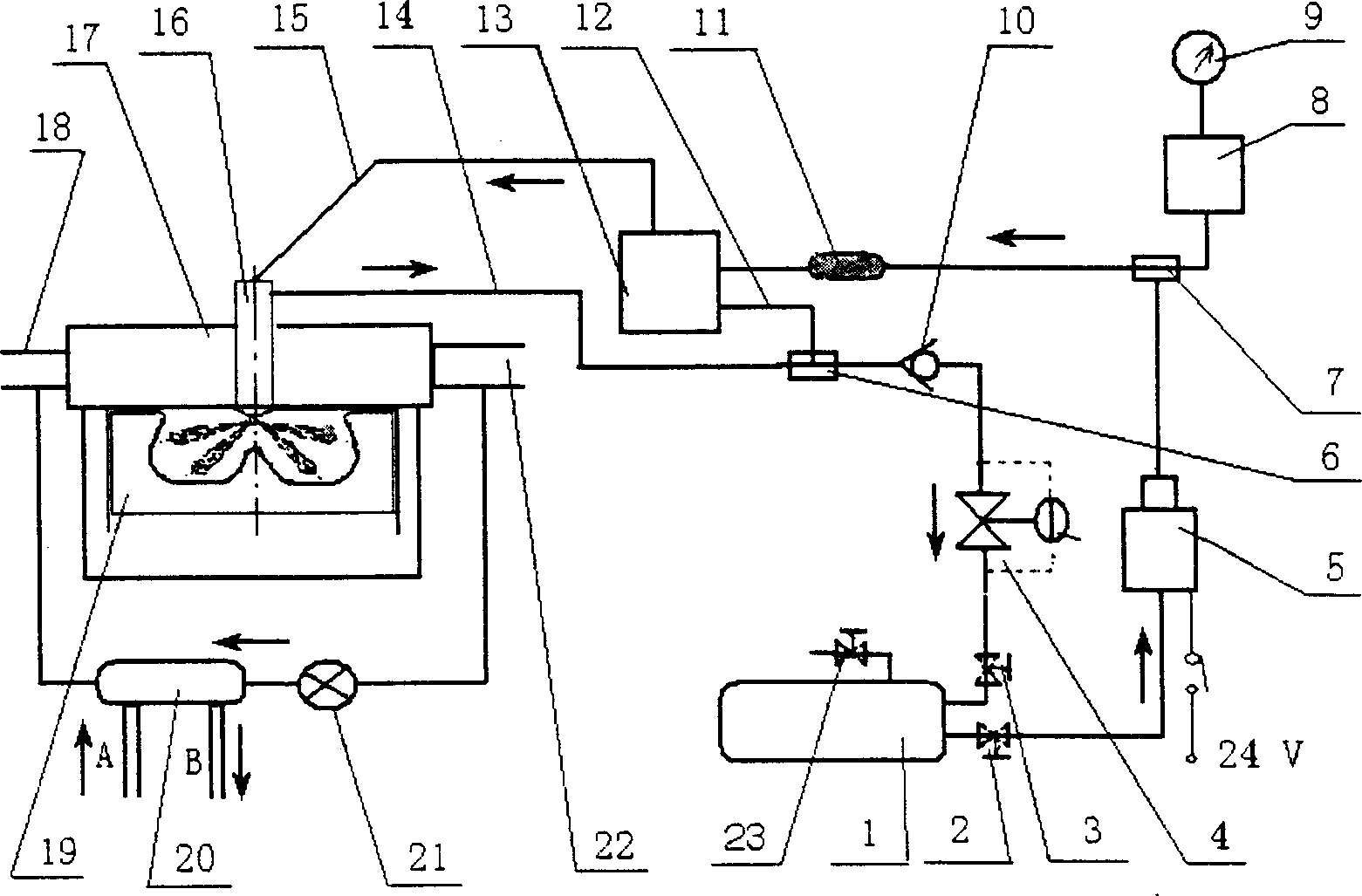
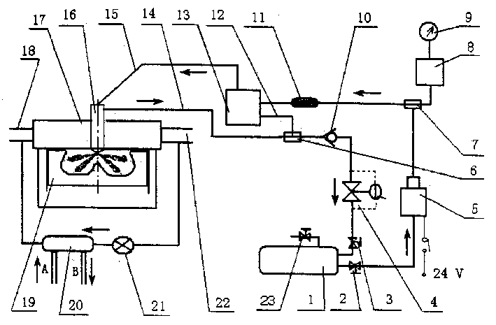
[0009] like figure 1 As shown, the present invention includes: DME storage tank 1, liquid outlet valve 2, return valve 3, pressure control valve 4, low-pressure fuel delivery pump 5, oil return tee joint 6, tee joint 7, pressure accumulator 8, pressure Table 9. Check valve 10, fuel filter 11, fuel injection pump return pipe 12, enhanced fuel injection pump 13, fuel injector return pipe 14, high-pressure fuel pipe 15, super multi-hole injector 16, cylinder head 17, inlet Gas pipe 18, combustion chamber 19, exhaust gas recirculation cooler 20, exhaust gas recirculation control valve 21, exhaust pipe 22, liquid filling valve 23, the connection method is: DME storage tank 1 passes liquid outlet valve 2 and low-pressure fuel delivery pump 5, the outlet of the low-pressure fuel delivery pump 5 is connected with the fuel filter 11 and the enhanced fuel injection pump 13 through the tee joint 7 to form a low-pressure fuel delivery system. The fuel injectors 16 are connected to form a...


PUM


Abstract

The dimethyl ether engine high-efficiency ultralow-discharge combustion system belongs to the field of internal combustion engine. The invented DME storage tank is connected with low-pressure fuel conveying pump by means of liquid outlet valve, the output of the low-pressure fuel conveying pump is connected with intensified fuel-spraying pump via one end of T-junctor and fuel filter, the outlet of intensified fuel-spraying pump is connected with ultramultinozzle fuel-spraying device via high-pressure fuel pipe, said ultramultinozzle fuel-spraying device is set on the cylinder cover of engine and is matched with combustion chamber, the outlet of waste gas recirculation control valve is connected with inlet of waste gas recirculation cooling device, and its inlet is connected with dischargetube.

Description

technical field [0001] The invention relates to a dimethyl ether engine combustion system, in particular to a dimethyl ether engine high-efficiency and ultra-low emission combustion system, which belongs to the field of internal combustion engines. Background technique [0002] As the vehicle engine with the highest thermal efficiency, the compression ignition engine has been highly valued by people. After several generations of hard work, the traditional combustion system has been developed relatively well. However, in recent years, the shortage of oil resources in the world, the sharp fluctuation of oil prices and the increasingly stringent emission regulations of various countries have brought new challenges to the research on alternative fuels and low-emission combustion of diesel engines. The dimethyl ether fuel that can be produced from coal, natural gas, and biomass is a new alternative fuel for automobiles that has emerged in recent years. Dimethyl ether is gaseous...

Claims


Application Information

Patent Timeline
IPC IPC(8): F02M21/02
CPCY02T10/32Y02T10/30
Inventor 黄震乔信起宋钧周校平张武高
Owner SHANGHAI JIAO TONG UNIV
Learn More