Coaxial flexible piezoelectric cable polarizer, polarizing method, defect detector, and defect detecting method

A defect detection and piezoelectric technology, applied in the manufacture/assembly of piezoelectric/electrostrictive devices, piezoelectric/electrostrictive/magnetostrictive devices, measuring devices, etc. Flexible piezoelectric body 2, can not be polarized, can not complete the cable and other problems

Inactive Publication Date: 2004-08-11
PANASONIC CORP
View PDF1 Cites 5 Cited by
  • Summary
  • Abstract
  • Description
  • Claims
  • Application Information

AI Technical Summary

Problems solved by technology

As a result, the coaxial flexible piezoelectric body 2 cannot be polarized because a high voltage cannot be applied between the core electrode 1 and the outer electrode 4 (usually a length of several hundred m or more)
In addition, because the presence of defects cannot be detected without applying a high voltage between the core electrode 1 and the outer electrode 4, in other words, if a high voltage is not applied, in addition to being unable to polarize, it cannot be completed as a coaxial flexible piezoelectric body. cable, so make the manufacturing unstable and the yield drop, so it is better to determine the defect location before polarization

Method used


Image

  • Coaxial flexible piezoelectric cable polarizer, polarizing method, defect detector, and defect detecting method
  • Coaxial flexible piezoelectric cable polarizer, polarizing method, defect detector, and defect detecting method
  • Coaxial flexible piezoelectric cable polarizer, polarizing method, defect detector, and defect detecting method

Examples


Embodiment 1

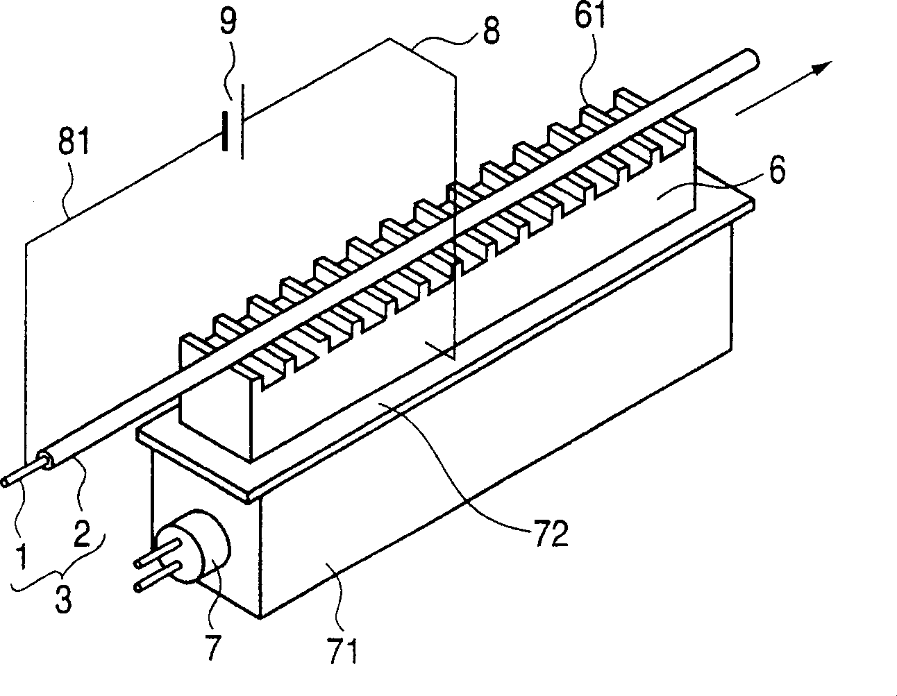
[0063] figure 1 It is a schematic appearance diagram showing the configuration of the polarizing device in Example 1 of the present invention. A coaxial flexible piezoelectric body is formed facing the core electrode 1 . This molded body is referred to as a piezoelectric tube 3, and a helical metal wire or a bundle of thin metal wires is used as the core electrode 1. Used in polymer masterbatches such as epoxy resin, amino resin, chloroprene rubber, chlorinated polyethylene resin, etc., which are filled with ceramic piezoelectric body powder such as lead zirconate titanate or composite piezoelectric body or macromolecule such as PVDF The piezoelectric body serves as a flexible piezoelectric body.

[0064] The piezoelectric tube 3 is arranged on the piezoelectric tube passage portion 61 provided on the bulk conductor 6, and the piezoelectric tube 3 is moved by moving means (not shown in the figure). The piezoelectric tube passage portion 61 is formed in a concavo-convex sha...

Embodiment 2

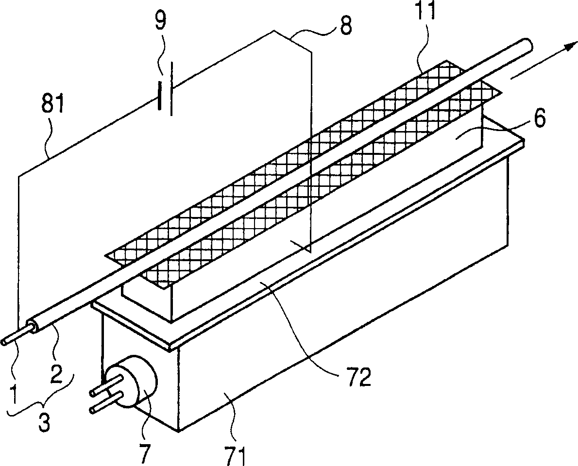
[0068] figure 2 It is a schematic appearance diagram showing the configuration of the coaxial flexible piezoelectric body polarizer in the second embodiment of the present invention. In the second embodiment, the metal mesh 10 is used as the piezoelectric body tube passage portion. The piezoelectric tube 3 is arranged on the metal mesh 10 provided on the surface of the bulk conductor 6, and moved by moving means (not shown). The surface of the metal mesh 10 is formed in a concave-convex shape. Since the metal mesh 10 is used to form the unevenness, it is not necessary to process the arrangement surface of the piezoelectric tube 3 into a concave-convex shape, so the gap between the piezoelectric tube 3 and the piezoelectric tube passage portion (in the embodiment, the metal mesh 10) can be reduced. Friction, so that the piezoelectric tube 3 can be moved with a very small picture.

[0069] Conductors such as iron, stainless steel, copper, brass, and aluminum are used as the ...

Embodiment 3

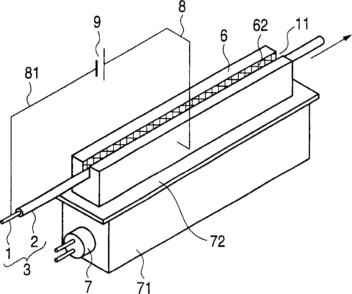
[0071] image 3 It is a schematic appearance diagram showing the configuration of the coaxial flexible piezoelectric body polarizer in Example 3 of the present invention. Grooves 11 are provided in the bulk conductor 6 , the passage portion of the piezoelectric tube 3 is changed to the groove 11 , and the inner surface of the groove 11 is formed into a concavo-convex shape 62 . When the bulk conductor 6 is heated to heat the piezoelectric tube 3 arranged in the groove 11 of the bulk conductor 6 , the piezoelectric tube 3 is heated by the bottom and both walls of the groove 11 . Since the piezoelectric body tube 3 is heated more uniformly, it is possible to polarize the coaxial flexible piezoelectric body 2 at a necessary temperature. In addition, the upper part is opened in advance, and the piezoelectric tube 3 can be easily arranged from the upper part of the tank 11 . In addition, since the inner surface of the groove 11 serving as the passage portion of the piezoelectric ...


PUM

PropertyMeasurementUnit
thicknessaaaaaaaaaa

Abstract

The invention provides a defect inspecting apparatus and a defect detecting method for specifying a position of a defect before polarization when the defect is included in a coaxial flexible piezoelectric member. Further, when a piezoelectric tube is moved in polarization, a friction force is produced between the coaxial flexible piezoelectric member and a block-like conductor and therefore, a large force is needed in moving the piezoelectric tube. The invention provides a polarizing apparatus and a polarizing method capable of moving the piezoelectric tube even by a small force. <??>There are provided a defect detecting apparatus of a coaxial flexible piezoelectric member having a constitution of applying a direct current to a coaxial flexible piezoelectric member while moving a piezoelectric tube arranged at a hole of inspecting electrode means and a marking apparatus for marking a defect portion. Thereby, when a defect is present at a portion thereof arranged at the hole of the inspecting electrode means, electricity is discharged at the defect portion and therefore, the defect portion can be specified and the mark can be attached to the defect portion. Further, a conductive block provided with a path portion of the piezoelectric tube is divided. By dividing the block-like conductor by a plural number, a friction force between the block-like conductor per divided one and the piezoelectric tube is reduced. Further, the piezoelectric tube can be moved by a small force by a pulley arranged at a fold back portion of the piezoelectric tube.

Description

technical field [0001] The present invention relates to a polarization device for a coaxial flexible piezoelectric cable, and also relates to a defect detection device and a defect detection method for the cable. Background technique [0002] This coaxial flexible piezoelectric cable in the prior art is as Figure 7 As shown, the outer electrode 4 is formed on the outer surface of the flexible piezoelectric tube 3 formed around the core electrode 1 , and the protective coating layer 5 is formed around the outer electrode 4 . [0003] Flexible piezo cables are usually polarized in the following way [0004] In Document 1 (Piezoelectric composite materials, powders and industry in the space of piezoelectric ceramic powder and synthetic rubber, vol. 22, pp. 50-56, No. 1, 1990), it is given that the process of passing between the core electrode 1 and the outer electrode 4 A high voltage is applied to polarize the coaxial flexible piezoelectric body 2 . This convenient method i...

Claims


Application Information

Patent Timeline
Patent Type & Authority Applications(China)
IPC IPC(8): G01R29/22H01L41/087H01L41/257H01L41/45
CPCH01L41/087G01R31/021H01L41/257H01L41/45Y10S310/80G01R31/083Y10T29/42G01R31/58H10N30/60H10N30/045H10N30/098H10N30/01
Inventor 海老泽满男长井彪杉森透
Owner PANASONIC CORP
Why Eureka
Try Eureka