

Electric power generating system for a vehicle
A technology for power generation systems and vehicles, applied in control systems, vehicle energy storage, vehicle components, etc., can solve the problems of unfavorable and difficult to adopt ferromagnetic cores
- Summary
- Abstract
- Description
- Claims
- Application Information
AI Technical Summary
Problems solved by technology
Method used
Image

Examples
no. 1 example
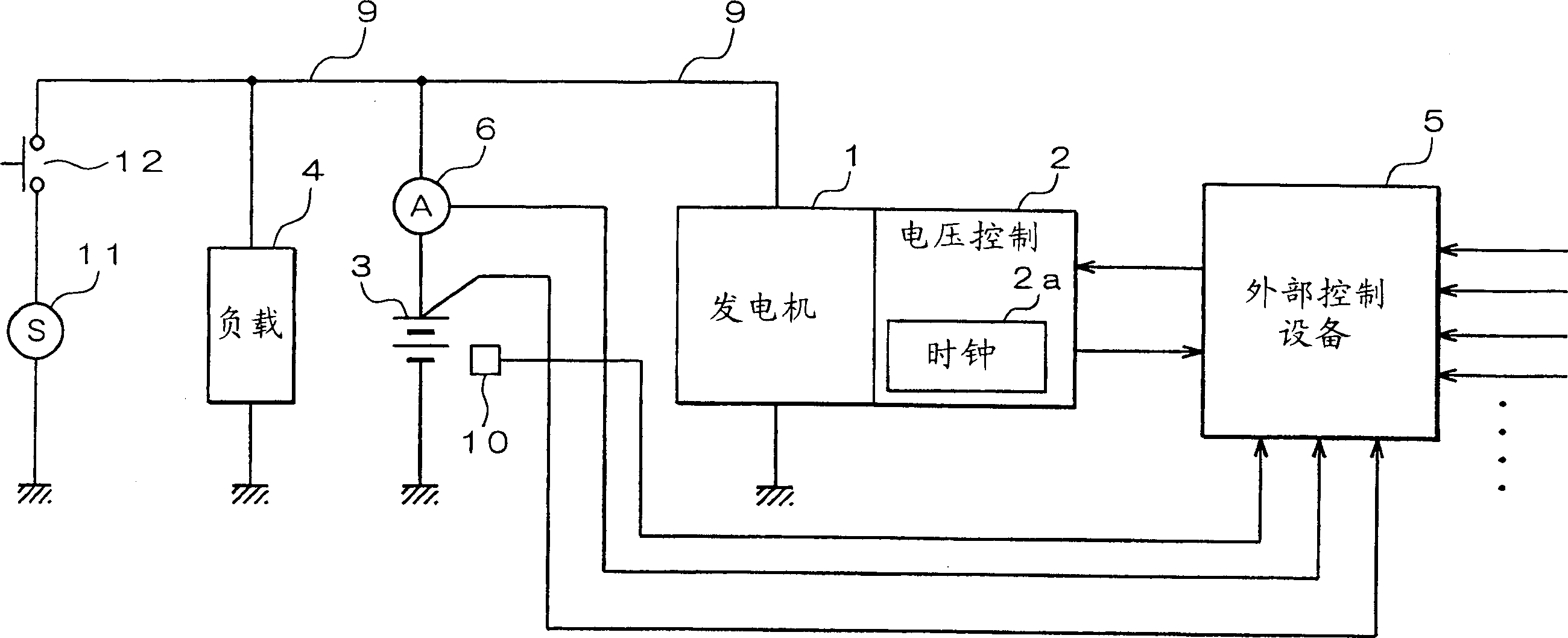
[0032] first reference figure 1 , a power generation system for a vehicle is configured with a generator 1, a voltage control device 2, a battery 3, an electrical load 4, and an electronic control unit (ECU) 5 for an internal combustion engine (not shown).
[0033] The generator is driven to rotate by the engine, and generates electric power for charging the battery 3 and electric power for operating the electric load 4 .
[0034] The voltage control device 2 controls the generator 1 to adjust the output voltage of the generator 1 to a predetermined value by controlling the conduction state of the excitation current flowing in the generator 1 to the excitation coil. In this voltage control device 2, a power supply circuit that generates an operating voltage of an element circuit, a power device such as a power transistor for controlling conduction of an excitation current, a logic circuit for performing this conduction control, and the like are realized by a CMOS-IC . The v...
no. 2 example
[0087] Because the noise absorbing ability is lowered in the case of deterioration of the battery 3, the variation in the output voltage of the generator 1 becomes large. In this case, it is also desirable to prohibit the output of the power generation suppression signal.
[0088] Figure 15A and 15B show changes in battery terminal voltage due to the presence or absence of battery 3 degradation. When the battery 3 deteriorates, the internal resistance increases. The internal impedance of a new undegraded battery 3 is R1 ( Figure 15A ), the internal impedance of the degraded battery 3 is R2 (FIG. 15B).
[0089] Assuming that the negative surge current flowing when the inductive electrical load 14 is turned on or off is i, the ideal terminal voltage of the battery 3 is V batt , then the battery voltage V of the undegraded battery 3 b1 becomes V batt -i×R1, battery voltage V of degraded battery 3 b2 becomes V batt -i×R2. Comparing these voltages, since there is a relat...
PUM
 Abstract
Description
Claims
Application Information