Lithographic apparatus and device manufacturing method

A kind of equipment and technology of lithography projection, which is applied in the direction of microlithography exposure equipment, photomechanical equipment, photolithography exposure device, etc., can solve the problems of beam uniformity and angular distribution influence, etc.

Inactive Publication Date: 2004-11-03
ASML NETHERLANDS BV +1
View PDF8 Cites 5 Cited by
  • Summary
  • Abstract
  • Description
  • Claims
  • Application Information

AI Technical Summary

Problems solved by technology

[0023] In addition, it has been found that in current systems the change of position, i.e. the translation of the beam in the lateral direction, l

Method used


Image

  • Lithographic apparatus and device manufacturing method
  • Lithographic apparatus and device manufacturing method
  • Lithographic apparatus and device manufacturing method

Examples


Embodiment 1

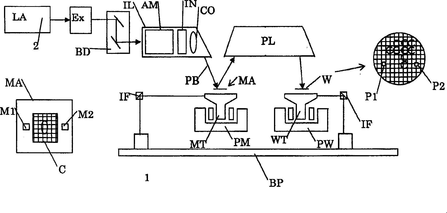
[0039] figure 1 A lithographic projection apparatus 1 of a specific embodiment of the present invention is schematically represented. The equipment includes:

[0040] - A radiation source Ex, BD, IL for providing a projection beam PB of radiation (eg light in the deep ultraviolet region). In this particular case, the radiation system also comprises a radiation source LA;

[0041] - a first stage (mask table) MT provided with a mask holder for holding a mask MA (eg a reticle) and with a first positioning device for precisely positioning the mask relative to the object PL Device PM connection;

[0042] - a second stage (substrate table) WT provided with a substrate holder for holding a substrate W (e.g. a resist-coated silicon wafer) and with a second positioner for precise positioning of the substrate relative to the object PL Device PW connection; and

[0043] - A projection system ("lens") PL for imaging the radiation portion of the mask MA onto a target portion C of th...


PUM


Abstract

A lithographic projection apparatus comprising: a radiation source for providing a projection beam of radiation; a support structure for supporting patterning means, the patterning means serving to pattern the projection beam according to a desired pattern; a substrate table for holding a substrate; a projection system for projecting the patterned beam onto a target portion of the substrate; said radiation source further comprising: an illumination system for conditioning said beam of radiation so as to provide a conditioned radiation beam so as to be able to illuminate said patterning means; said illumination system defining a plane of entrance wherein said radiation beam enters said illumination system; and a beam delivery system comprising redirecting elements for redirecting and delivering said projection beam from a radiation source to said illumination system. The lithographic projection apparatus is characterized in that the said beam delivery system comprises an imaging system for imaging said radiation beam from an object plane located at a distance from said plane of entrance to an image plane located near or at said plane of entrance. In this way the influence of laser pointing drift on both beam position and pointing drift at said entrance is highly decreased.

Description

technical field [0001] The invention relates to a lithographic projection device, comprising: [0002] - a radiation source for providing a radiation projection beam; [0003] - a support structure for supporting a patterning device for patterning the projected light beam according to a desired pattern; [0004] - a substrate table for holding the substrate; [0005] - a projection system for projecting a patterned light beam onto a target portion of a substrate; [0006] The radiation source further comprises: [0007] - an illumination system for conditioning said radiation beam to provide a conditional radiation beam capable of illuminating said patterning device; said illumination system defining an entrance plane, wherein said radiation beam enters said illumination system; and [0008] - A beam delivery system comprising a diverting element for diverting and delivering said projection beam from a radiation source to said illumination system. Background technique ...

Claims


Application Information

Patent Timeline
IPC IPC(8): G03F7/20H01L21/027
CPCG03F7/70158G03F7/70141G01R1/06733G01R1/06716G01R31/36
Inventor A·E·A·库伦E·W·M·克诺斯M·莫
Owner ASML NETHERLANDS BV
Why Eureka
Try Eureka