Low temperature and low noise factor amplifying circuit

A noise figure and amplifying circuit technology, applied in electrical components, transmission systems, etc., can solve the problems that the noise circuit area exceeds the application range, the electrical index cannot meet the requirements of high-performance communication receivers, and the circuit noise cannot be achieved.

Active Publication Date: 2004-11-10
TSINGHUA UNIV
View PDF0 Cites 13 Cited by
  • Summary
  • Abstract
  • Description
  • Claims
  • Application Information

AI Technical Summary

Problems solved by technology

[0004] Conventional low-noise design generally adopts two forms in the mobile communication frequency band: microstrip circuit and microwave monolithic integrated circuit based on CMOS technology, but neither of these two methods can achieve optimal performance
Even if a substrate microstrip circuit with a dielectric constant as high as 10 and a thickness of only 0.5mm is used, the on-chip wavelength in the radio frequency range is generally 140mm, and the length of such a 1/4 wavelength converter is 35mm, causing the area of ​​the noise circuit to exceed the application range; However, the MMIC circuit can only be realized by an on-chip microstrip pattern with a very low Q value because of its input matching, so that the noise performance of the whole machine becomes the price of

Method used


Image

  • Low temperature and low noise factor amplifying circuit
  • Low temperature and low noise factor amplifying circuit
  • Low temperature and low noise factor amplifying circuit

Examples


Embodiment Construction

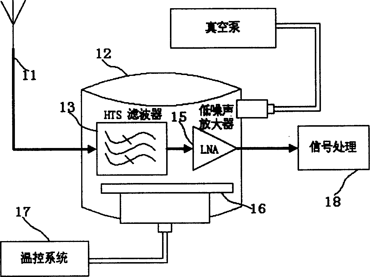
[0023] The specific embodiment of the present invention will be described with reference to the accompanying drawings. The present invention is suitable for radio frequency range (300MHz-3GHz).

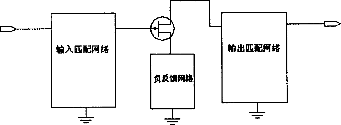
[0024] Such as figure 2 As shown, the present invention uses a field effect transistor HEMT as an amplifying device, an input matching network is between the gate of the field effect transistor and the signal input end, an output matching network is between the drain and the signal output end, and the source is connected to the ground negative feedback network.

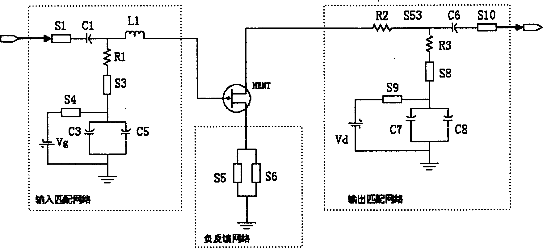
[0025] Such as image 3 As shown, the input matching network is a T-type impedance network. The input matching network can be divided into AC parts, including: microstrip line S1, microwave capacitor C1, spiral inductance coil L1, resistance R1 and microstrip line S3; and DC bias part, including: filter capacitors C3, C5 and the introduction of DC bias The microstrip line S4 of the power supply. The AC part involves onl...


PUM


Abstract

The invention is a low-temperature extremely low-noise coefficient amplifying circuit and its character: it adopts microband mixing circuit, adopts high-Q value spiral inductance coil and high-Q value capacitor in the input matching network in order to reduce input circuit loss and then noise; the spiral inductance coil's two ends adopts double parallel microbnd line structure, reducing parasitic parameters; the microband length of the negative feedback network is less than 1/10 working wavelength, reducing parasitic vibration; it adopts small resistances in input and output matching networks, enhancing value of real part of impedance; in the output matching network, the resistances in series with main lines and branch lines are proper to make the gain larger; the input and output matching networks is connected to 1/4 working wavelength branch lines, reducing circuit size to make the circuit able to work at low temperature for a long period. It can meet the requirements of low noise, larger gain, low standing wave ratio, working at low temperature for a long time, etc.

Description

technical field [0001] The low-temperature and extremely low noise factor amplifying circuit relates to the technical field of microwave communication circuits, in particular to the technical field of design of receiver front-end amplifying circuits. Background technique [0002] Wireless communication, especially the spread spectrum wireless communication technology has been widely promoted and paid great attention since it came into practical use in the 1960s. The main part of the wireless communication hardware is the RF front-end, which is composed of an amplifier circuit and a pre-filter circuit. See figure 1 , the signal is received by the radio frequency antenna 11 and input to the front-end processing circuit through the signal cable. The front-end processing circuit is composed of a filter 13 and a low-noise amplifier 15. It works in a low-temperature vacuum chamber 12. The temperature controller 17 controls the vacuum chamber to maintain a working temperature of 7...

Claims


Application Information

Patent Timeline
IPC IPC(8): H04B1/10
Inventor 曹必松张晓平高飞郜龙马高葆新
Owner TSINGHUA UNIV
Why Eureka
Try Eureka