Drying room exhaust gas purification and energy recovery system and apparatus

A waste gas purification and energy recovery technology, which is applied in chemical instruments and methods, dispersed particle separation, separation methods, etc., can solve the problems of large energy consumption, increased production costs, and high processing costs, and achieves high heat energy utilization and convenient device installation , the effect of small space volume

Inactive Publication Date: 2004-11-17
杭州天人环保设备有限公司
View PDF1 Cites 25 Cited by
  • Summary
  • Abstract
  • Description
  • Claims
  • Application Information

AI Technical Summary

Problems solved by technology

The general catalytic combustion method requires relatively stable high-concentration exhaust gas, followed by a catalyst with good activity and stability and a heat exchanger with high heat exchange efficiency. It has high requirements for the treatment of exhaust gas and equipment, relatively high processing costs, and difficult utilization of heat energy.
[0005] The utility model patent specification with the patent No. 93222819.4 discloses an air purification device for treating organic waste gas. The device is composed of an adsorption bed filled with honeycomb activated carbon and a catalytic combustion chamber. The organic waste gas is sucked in by the adsorption fan and filtered through a pre-filter. , enter the activated carbon adsorption bed for adsorption. There are two sets of adsorption beds, which are exchanged for adsorption and desorption. The desorbed gas enters the catalytic combustion chamber for combustion, and the heat energy generated cannot be used. There are adsorption fans, desorption fans, and air coolers before and after. Three fans, high energy consumption
[0006] For industries such as printing iron, finishing, and baking paint, the drying room used needs to consume a lot of energy for heating, and at the same time, a large amount of organic waste gas is generated in the production process, which consumes a lot of energy and causes serious pollution, which increases the production cost. At present, there is no better one in China. solution to this problem

Method used


Image

  • Drying room exhaust gas purification and energy recovery system and apparatus
  • Drying room exhaust gas purification and energy recovery system and apparatus

Examples


Embodiment Construction

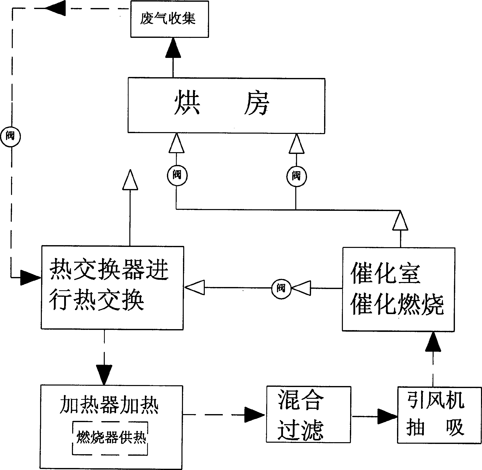
[0024] A system for purification of waste gas in a drying room and energy recovery and utilization, such as figure 1 As shown, the solid arrow in the figure indicates the flow direction of exhaust gas, and the hollow arrow indicates the flow direction of purified gas, forming a recycling system. After being collected, the exhaust gas discharged from the drying room enters the heat exchanger for heat exchange and pre-heating, and the pre-heated exhaust gas enters the heating chamber Heating, the heating chamber provides heat in the form of heat exchange through the burner set inside it, and a small part can also enter the burner to participate in combustion; after the heated exhaust gas is mixed with the exhaust gas burned by the burner, the temperature will reach 270-370 ℃, the filtered exhaust gas is extracted by the induced draft fan and enters the catalytic chamber for catalytic combustion; the temperature of the purified gas after combustion can reach 400-550 ℃, and most of...


PUM


Abstract

The invention discloses a system and device for drying room waste gas processing and energy reclaiming, it uses circular system to combine heat conversion, heating and catalyzing combustion together, which includes: (1) the waste gas discharged form the drying room is preheated in the heat converter; (2) the preheated gas is heated in the heating room; (3) the waste gas is filtered and extracted into the catalyst room to be carried on catalyzing combustion; (4) the purified gas provides heat in the drying room; the residue gas enters the heat converter and provides heat for the waste gas and then they are discharged off. The structure is compact, the space if small, the assembly is convenient; the heat energy utilization efficiency is high.

Description

technical field [0001] The invention relates to an environmental protection purification treatment system, in particular to a system and a device for purification treatment of waste gas in a drying room and energy recovery and utilization. Background technique [0002] At present, the commonly used organic waste gas treatment and purification methods are: [0003] 1. The thermal combustion method is customarily called the direct combustion method. This method uses the principle that the molecular chains of organic waste gas are easily broken at high temperatures, and uses a heat source to heat the organic waste gas to about 760-850°C. , in order to achieve the desired governance effect. The high-temperature gas generated after the waste gas is decomposed is provided to the heat-requiring equipment for utilization. The advantage of this method is that the one-time investment is low; the disadvantage is that the operation energy consumption is high, and the secondary polluti...

Claims


Application Information

Patent Timeline
Patent Type & Authority Applications(China)
IPC IPC(8): B01D53/72B01D53/86
Inventor 张正纲
Owner 杭州天人环保设备有限公司
Why Eureka
Try Eureka