One-dimensional moving three-dimensional rotating parallel machine tool

A three-dimensional rotation and parallel technology, which is applied in metal processing, metal processing equipment, manufacturing tools, etc., can solve problems such as difficulty in ensuring high rigidity, complex NC programming, and unsuitable processing, and achieve good structural shock resistance and cutting stability , Good processing technology, convenient decoupling of position and posture

Inactive Publication Date: 2005-03-16
UNIV OF ELECTRONICS SCI & TECH OF CHINA
View PDF0 Cites 17 Cited by
  • Summary
  • Abstract
  • Description
  • Claims
  • Application Information

AI Technical Summary

Problems solved by technology

Although the composite structure can expand the range of rotation angles, the complex structure makes it difficult to ensure high rigidity, coupled with the mutual coupling of position and attitude, the NC programming is very complicated. Therefore, the parallel machine tool based on the Stewart platform is not suitable for processing large parts with complex surfaces.

Method used


Image

  • One-dimensional moving three-dimensional rotating parallel machine tool
  • One-dimensional moving three-dimensional rotating parallel machine tool
  • One-dimensional moving three-dimensional rotating parallel machine tool

Examples


Embodiment 1

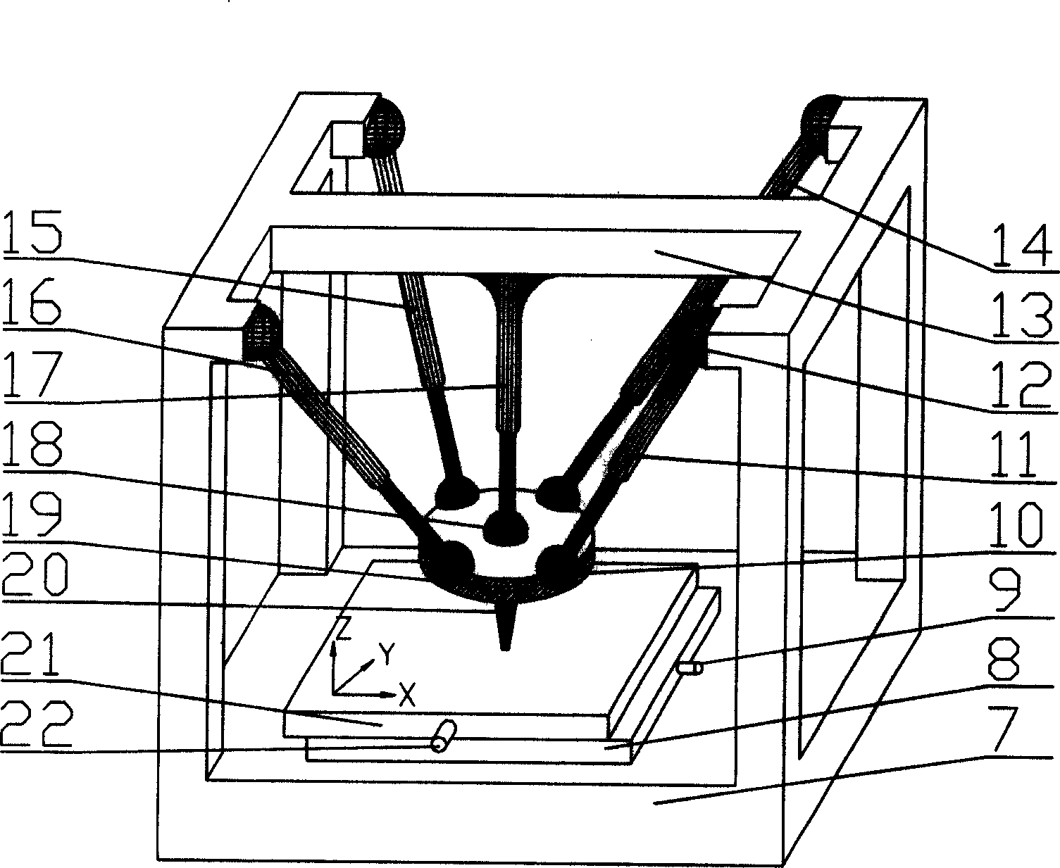
[0038] The general structure of embodiment one is as figure 2 As shown, in this embodiment, it includes a fixed table 13, a moving platform 19 for installing cutting tools, two-way mobile platforms 8 and 21 that can move along the X and Y directions, and a workbench for installing workpieces to be cut. It is characterized in that the fixed platform 13 is connected with the moving platform 19 by 5 legs, and the surrounding 4 telescopic legs (11, 14, 15, 16) are connected with the fixed platform 13 by a Hooke hinge or a spherical hinge (such as a spherical hinge 12) , the surrounding 4 telescopic legs (11, 14, 15, 16) are connected with the moving platform 19 by a ball joint (such as the ball joint 10). One end of the middle leg 17 is rigidly connected to the center of the fixed platform 13 , and the other end is connected to the moving platform 19 through a ball joint 18 . Thus a space parallel closed-chain structure is formed, and the two-way mobile platforms 8 and 21 that c...

Embodiment 2

[0042] The general structure of embodiment two is as Figure 4 As shown, in the present embodiment, the machine tool bed 23 and the frame 32 form a fixed platform, and the fixed platform and a moving platform 37 for installing cutting tools, fixed-length peripheral legs (27, 30, 33, 34), and an intermediate leg 35 form a space Parallel closed chain mechanism. One end of the legs (27, 30, 33, 34) around the fixed length is connected with a slide block (such as a slide block 29) by a Hooke hinge or a ball joint (such as a ball joint 28), and the slide block is driven by a servo motor (such as a servo motor 31). ) Driven by the lead screw nut drive. The moving platform 37 is connected with the fixed-length surrounding legs (27, 30, 33, 34) by a ball joint (such as the ball joint 26). The middle leg 35 is rigidly connected to the center of the frame 32 , and the other end of the middle leg 35 is connected to the moving platform 37 through a ball joint 36 . When the displacement...

Embodiment 3

[0043] The general structure of embodiment three is as Figure 5 As shown, in the present embodiment, the lower platform 51 in the two-way mobile platform, the moving platform 56 on which the cutting tool is installed, the surrounding telescopic legs (43, 45, 50, 53), and the middle leg 54 form a space parallel closed-chain mechanism. And the two-way mobile platform can translate along the X and Y axis directions under the drive of the lead screw nuts driven by the servo motors 47 and 52 . Wherein the lower platform 51 in the two-way mobile platform is connected with the surrounding telescopic legs (43, 45, 50, 53) by a Hooke hinge or a ball joint (as the ball joint 44), and the moving platform 56 is connected with the surrounding telescopic legs (43, 53). 45, 50, 53) are connected by a ball joint (such as the ball joint 42). The middle leg 54 is rigidly connected to the center of the lower platform 51 in the two-way moving platform, and the other end of the middle leg 54 is ...


PUM


Abstract

The invention relates to a kind of shunt machine table which moves in one-dimensional and rotates in three-dimensional. It sets a space shunting device on the horizontal moving flat on which is fixed cutter. The space shunting device is made of five legs which connect to the moving flat through their tops. One end of the center leg is fixed firmly to the center of five legs connecting device, the other end of it connects to the moving flat through round hinge. The other four driving legs connect to the moving flat through round hinges. The device has advantages such as simple structure, flexible process, high precision, high process speed, high performance, decouple and digit controlling expediently. So it can meet the customer's demand of multi-shaft controlling digitally the big accessory that has many crooked faces.

Description

Technical field [0001] The invention belongs to the technical field of numerical control machine tool manufacturing, in particular to a parallel structure numerical control machine tool. Background technique [0002] In the field of mechanical manufacturing technology, the mechanical structure of traditional CNC machine tools is to arrange components along the X, Y, and Z axes of the Cartesian (rectangular) coordinate system, and the components are connected in series. This series structure design makes the machine tool prone to errors. Accumulate and reduce the machining accuracy. Because the components are not only subjected to tension and pressure, but also subjected to bending moments and torques, the overall rigidity of the machine tool is reduced. Deterioration of academic performance. Especially when the movement speed of the machine tool is high and the workpiece is large, these shortcomings are even more prominent. [0003] In order to meet the increasingly comple...

Claims


Application Information

Patent Timeline
Patent Type & Authority Applications(China)
IPC IPC(8): B23Q41/04
Inventor 范守文李辉王小兵吴献钢陈畅袁太文洪涛
Owner UNIV OF ELECTRONICS SCI & TECH OF CHINA
Why Eureka
Try Eureka