Method for manufacturing minitype liquid methanol fuel cell

A technology of methanol fuel cell and manufacturing method, which is applied to fuel cell parts, fuel cells, aqueous electrolyte fuel cells, etc., can solve the problems of reducing the physical size of the battery, achieve low manufacturing cost, increase structural strength, and be easy to design Effect

Inactive Publication Date: 2005-03-16
HARBIN INST OF TECH
View PDF0 Cites 14 Cited by
  • Summary
  • Abstract
  • Description
  • Claims
  • Application Information

AI Technical Summary

Problems solved by technology

However, fabrication of micro fuel cells for portable energy is not simply a matter of reducing the physical size of the battery
For example, the processing of graphite flow field structure will be limited by the brittleness of graphite and the mold
Previous manufacturing methods for large-scale fuel cells cannot be directly applied to the processing of micro-fuel cells

Method used


Image

  • Method for manufacturing minitype liquid methanol fuel cell
  • Method for manufacturing minitype liquid methanol fuel cell
  • Method for manufacturing minitype liquid methanol fuel cell

Examples


Embodiment 1

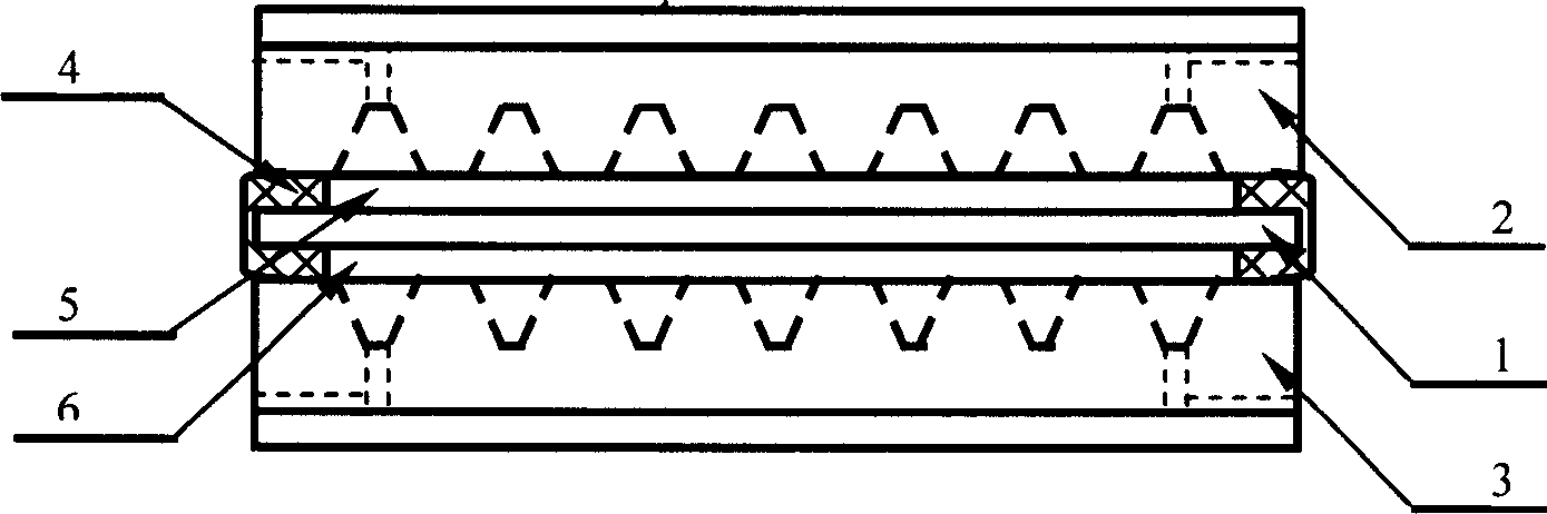
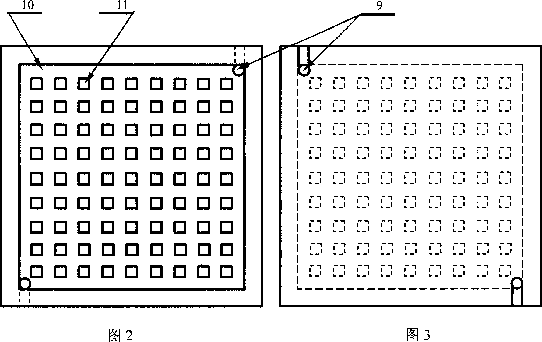
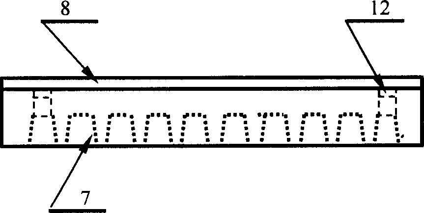
[0018] Example 1: Combining figure 1 As shown in Fig. 2, the composition of the micro liquid methanol fuel cell includes a membrane electrode 1 and bipolar plates 2, 3 positioned on both sides of the membrane electrode. Resin glue4. Bipolar plates are made from silicon wafers. The silicon wafer was ultrasonically cleaned with toluene, acetone and ethanol respectively. The cleaned silicon wafers are placed in an oxidation furnace, and the temperature of the oxidation furnace is controlled at 1180°C. The temperature of the water bath is 95-97°C, and the oxygen flow rate is 1l / min. layer of silicon dioxide. The photolithographic method is used to carve the pattern of the flow chamber and the oxide layer of the liquid diversion channel, and the support points 11 in the flow chamber may be distributed in a point form or in a serpentine form. Then use HF acid to etch the silicon dioxide to open the window for etching the silicon body. The silicon body is etched with a KOH solu...

Embodiment 2

[0019] Embodiment 2: Combination figure 1 As shown in Fig. 2, the composition of the micro liquid methanol fuel cell includes a membrane electrode 1 and bipolar plates 2, 3 positioned on both sides of the membrane electrode. Resin glue4. A bipolar plate is made from a silicon wafer with a thickness of 10mm×10mm and a thickness of 500 microns. The silicon wafer was ultrasonically cleaned with toluene, acetone and ethanol respectively. The cleaned silicon wafers are placed in an oxidation furnace, and the temperature of the oxidation furnace is controlled at 1180°C. The temperature of the water bath is 97°C, and the oxygen flow rate is 1l / min. Floor. The photolithographic method is used to engrave the pattern of the flow chamber and the oxide layer of the liquid channel. The support points in the flow chamber can be distributed in a point-like manner. The support points are 0.4mm×0.4mm, and the distance between the support points is also 0.4mm. Then use HF acid to etch the ...

Embodiment 3

[0020] Embodiment 3: Serpentine flow field structure. Change the graphic design of the lithography mask. A photolithographic mask with a serpentine structure is selected, and other process steps are the same as those in Embodiment 2.


PUM

PropertyMeasurementUnit
thicknessaaaaaaaaaa

Abstract

The invention is a manufacturing method for a micro liquid methanol fuel cell, using MEMS technique for processing bipolar plate which is pressed air tightly on membrane electrode and surrounding of fuel cell is sealed by resin glue. Use techniques of oxidation, lithographic process and silicon corrosion to manufacture bipolar plate, and its flow field and liquid inlet and outlet channel is plane arrangement, finally make glass and bipolar plate have bonding and manufacture sediment of vacuum metal layer. The invention can effectively finish the structure of flow field and electric current collection, reduce volume of fuel cell and is suitable for batch production.

Description

(1) Technical field [0001] The invention relates to a method for manufacturing a micro battery, in particular to a method for processing a micro liquid methanol fuel cell using micro-machining (MEMS) technology. (2) Background technology [0002] Direct methanol fuel cells (DMFCs) have inherent advantages as a miniature portable energy source. High specific energy and energy conversion efficiency are the main reasons for interest. At the same time, the fixed external structure and the liquid fuel that can be filled at any time also provide convenient conditions for users. However, fabrication of tiny fuel cells for portable energy is not simply about reducing the physical size of the battery. For example, the processing of graphite flow field structures will be limited by the brittleness of graphite and the limitations of molds. The previous manufacturing methods of large-scale fuel cells cannot be directly applied to the processing of micro-fuel cells. (3) Contents of ...

Claims


Application Information

Patent Timeline
Patent Type & Authority Applications(China)
IPC IPC(8): B81B5/00H01M4/88H01M8/1011
CPCY02E60/50Y02P70/50
Inventor 刘晓为张国威王喜莲田丽
Owner HARBIN INST OF TECH
Why Eureka
Try Eureka