Structure of flow field board for proton exchange film fuel cell

A proton exchange membrane and fuel cell technology, applied in fuel cell parts, fuel cells, battery electrodes, etc., can solve the problems of voltage instability, reaction dead zone, easy accumulation of water, etc., to increase the effective use area, speed up The effect of reaction rate and utilization improvement

Inactive Publication Date: 2005-03-30
ZHEJIANG UNIV
View PDF3 Cites 4 Cited by
  • Summary
  • Abstract
  • Description
  • Claims
  • Application Information

AI Technical Summary

Problems solved by technology

However, these patents have more or less deficiencies: for example, the airflow distribution of the bipolar plate is not uniform enough; the water generated by the reaction is easy to accumulate and difficult to discharge, and the design of the flow field structure is easy to cause reaction dead zone, voltage instability, etc., which affect the normal operation of the battery. performance

Method used


Image

  • Structure of flow field board for proton exchange film fuel cell
  • Structure of flow field board for proton exchange film fuel cell
  • Structure of flow field board for proton exchange film fuel cell

Examples


Embodiment

[0032] The natural high-purity graphite powder, polymer materials, additives, etc. are mixed in a certain proportion and then put into the mold, and the mold is put into the plate vulcanizing machine. Under 10~100MPa and 100~300℃, one-time compression molding becomes a composite double containing flow field. Plate products.

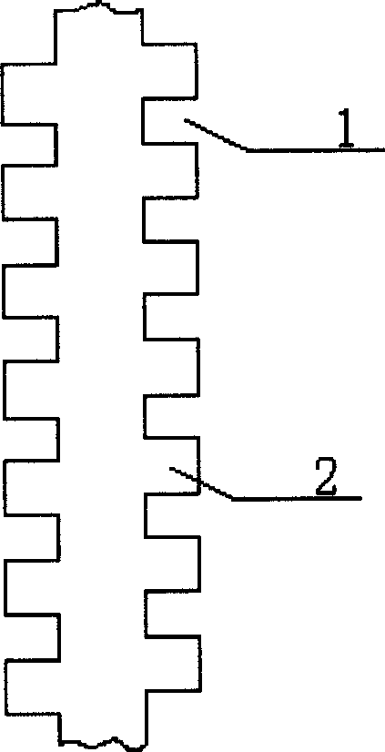
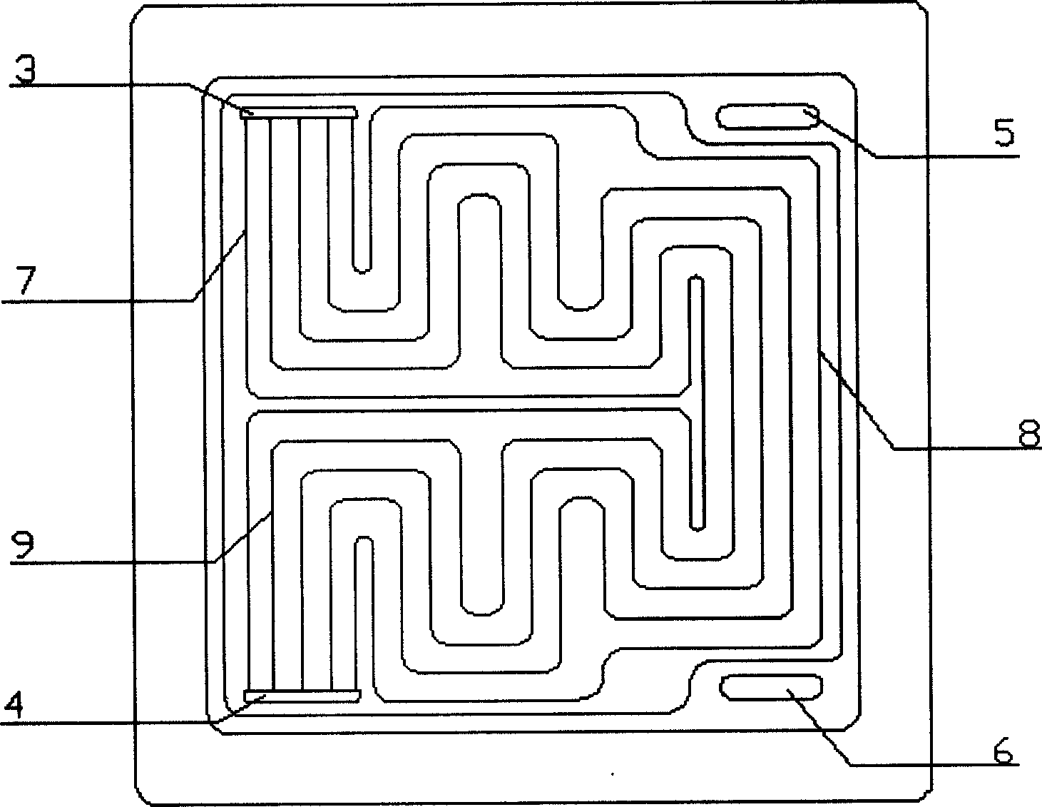
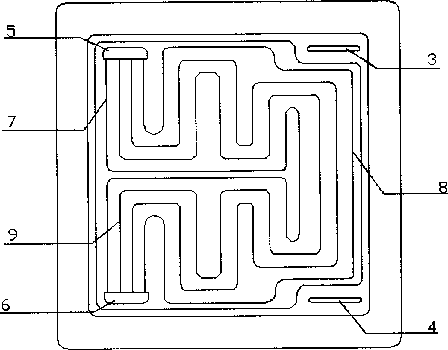
[0033] A flow field plate structure for a proton exchange membrane fuel cell includes a flow field plate body. The main body of the flow field plate is a flow guide bipolar plate, one side of which is a hydrogen flow field plate, and the other side is a flow field plate that guides air; Figure II It is the said hydrogen-conducting flow field plate. It is provided with a pair of diversion ports 3 and 4 for entering and exiting hydrogen, and they are distributed on the same side of the flow field plate. The hydrogen gas inlet and the hydrogen gas outlet are equal in size and shape. They are elongated rectangles with a width of 3mm and a length of 33mm. There a...


PUM

PropertyMeasurementUnit
widthaaaaaaaaaa
widthaaaaaaaaaa
depthaaaaaaaaaa

Abstract

Body of flow field board is made from material composed of processed natural graphite and high molecular material, and mold pressed at one time under high temp. There are hydrogen inlet, hydrogen outlet, air inlet and air outlet, circulating trough for water, water inlet and outlet, and diversion groove of connecting to air inlet and air outlet in flow field board. In the disclosed flow field board, there is each pair of air inlets and outlets, and hydrogen inlets and outlets in threadlike rectangle. Diversion groove for connecting to a pair of inlet and outlet is in streamline type parallel mode distribution structure in flow field. Width of groove is 1.0-3.5mm, depth is 0.3-0.6mm, and width of ridge is 1.0-5.0 mm. Features are: even air flow distribution, unobstructed for air flow, high use ratio of cross section, and steady operation.

Description

Technical field [0001] The present invention relates to fuel cell technology, in particular to the structure of a flow field plate for a proton exchange membrane fuel cell. Background technique [0002] With the rapid development of human society today, traditional energy sources such as coal, oil, and natural gas have become increasingly unable to meet the needs of the industrial society that has entered the 21st century. The energy resources that mankind currently relies on are entering the last decades of exhaustion, and the serious environmental pollution caused by these traditional energy sources has become an obstacle to the survival and development of human society. In view of this, all countries in the world are making every effort to find alternative energy sources in the future, so that they can fully replace the current traditional energy; up to now, the scientific community has agreed that hydrogen energy is an effective and clean alternative to gasoline, diesel and o...

Claims


Application Information

Patent Timeline
Patent Type & Authority Applications(China)
IPC IPC(8): H01M4/86H01M8/0258H01M8/0263
CPCY02E60/50
Inventor 方卫民刘晨
Owner ZHEJIANG UNIV
Why Eureka
Try Eureka