Digital control correcting method for resonance frequency of piezoelectric transducer and supersonic concentrator

A piezoelectric transducer and resonant frequency technology, applied in the ultrasonic field, can solve the problems of high labor intensity, low production efficiency, and increased production cost, and achieve low labor intensity, high correction efficiency, and low correction cost. Effect

Inactive Publication Date: 2005-04-06
HANGZHOU DIANZI UNIV
View PDF0 Cites 13 Cited by
  • Summary
  • Abstract
  • Description
  • Claims
  • Application Information

AI Technical Summary

Problems solved by technology

[0029] (2) Mass-produced ultrasonic generators cannot be directly matched with piezoelectric transducers and ultrasonic concentrators. The operating frequency and output impedance of each ultrasonic generator must be individually adjusted to match the corresponding piezoelectric transducers. The device matches the ultrasonic concentrator;
[0030] (3) Repeated disassembly and assembly of piezoelectric transducers and ultrasonic concentrators leads to high labor intensity and miserable workers;
[0031] (4) When the piezoelectric transducer and the ultrasonic concentrator are repeatedly disassembled, the piezoelectric ceramic sheet is often broken, resulting in an increase in production costs;
[0032] (5) There are many trimming processes and the production efficiency is extremely low;
[0033] (6) When repairing piezoelectric transducers and ultrasonic concentrators, since the correction position and margin are difficult to determine, it is often judged by the experience of technicians and workers, and the corrected piezoelectric transducers and ultrasonic concentrators cannot be known in time Whether the resonance frequency is close to the ideal frequency or far from it often leads to the scrapping of piezoelectric transducers and ultrasonic concentrators

Method used


Image

  • Digital control correcting method for resonance frequency of piezoelectric transducer and supersonic concentrator
  • Digital control correcting method for resonance frequency of piezoelectric transducer and supersonic concentrator
  • Digital control correcting method for resonance frequency of piezoelectric transducer and supersonic concentrator

Examples


Embodiment Construction

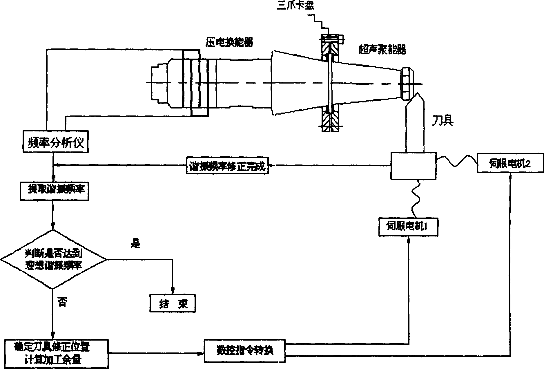
[0054]In the present invention, the piezoelectric transducer and the ultrasonic energy concentrator assembled together are installed on the three-jaw chuck or the special fixture of the numerically controlled lathe through the flange at the node of the ultrasonic energy concentrator. The positive and negative poles of the piezoelectric transducer are respectively connected to the positive and negative poles of the frequency (impedance) analyzer. While the piezoelectric transducer is rotating at high speed with the spindle of the CNC lathe, the frequency (impedance) analyzer measures the resonance frequency of the piezoelectric transducer and the ultrasonic concentrator in real time, and transmits the detected actual resonance frequency parameters to The computer calculates the difference between the actual resonance frequency and the theoretical resonance frequency, the correction position and correction margin of the piezoelectric transducer and the ultrasonic concentrator, an...


PUM


Abstract

The invention discloses a resonance frequency digital control amendment method of the piezoelectric transducer and super-sound concentrator. The piezoelectric transducer and super-sound concentrator assembled together are installed at the digital control lathe by the flange at the pitch point of the super-sound concentrator. The anode and the cathode of the piezoelectric transducer are respectively connected to the anode and the cathode of the frequency analyzer. The frequency analyzer is measured the resonance frequency of the piezoelectric transducer and super-sound concentrator at real time, and transferred the tested actual resonance frequency parameter to the computer to calculate out the difference value of the actual and theoretical resonance frequency, the amendment position and the amendment allowance of the piezoelectric transducer and super-sound concentrator. The piezoelectric transducer and super-sound concentrator are practiced precision finishing ultra-precision machining by the servo motor drive cutter to change their shape and size. The advantage of the invention are that the amendment efficiency is high; the amendment frequency is accurate; the piezoelectric transducer and super-sound concentrator will not be discarded as useless; the cost is low; the operation is simple; and the automatic amendment can be realize.

Description

technical field [0001] The invention relates to the ultrasonic field, in particular to a numerical control correction method for the resonant frequency of a piezoelectric transducer and an ultrasonic concentrator. Background technique [0002] There are thousands of products of intelligent ultrasonic equipment at home and abroad, and they have a wide range of applications and development prospects in countries all over the world. [0003] Intelligent ultrasound equipment refers to ultrasound equipment controlled by advanced electronic technology (computers, integrated circuits, new electronic devices, etc.). When the load and environmental conditions change, the static capacitance Co of the piezoelectric transducer and the resonant frequency f of the acoustic system will change, resulting in a drop in the acoustic power of the transducer, affecting the efficacy of the ultrasonic equipment, and even damaging the ultrasonic generator and piezoelectric transducer. Therefore, ...

Claims


Application Information

Patent Timeline
Patent Type & Authority Applications(China)
IPC IPC(8): B23Q15/20B23Q17/20G05B19/404
Inventor 张云电赵峰铁淑霞
Owner HANGZHOU DIANZI UNIV
Why Eureka
Try Eureka