
Light polarizing device, a method of continuously fabricating same, and reflective optical devices using same

一种偏振光学、元件的技术,应用在光学元件、偏振元件、光学等方向,能够解决不能获得格栅型的偏振光学元件、金属脱落、不能实现大面积化作业等问题

Inactive Publication Date: 2005-05-18
宫田 清藏 +1
View PDF5 Cites 6 Cited by
  • Summary
  • Abstract
  • Description
  • Claims
  • Application Information

AI Technical Summary

Problems solved by technology

[0008] However, if the manufacturing method of the grid-type polarizing optical element disclosed in the following Patent Document 4 is used, since the stretched transparent and flexible substrate is uniformly stretched by stretching, a uniform stretching force is also applied to the metal thin film on the substrate. , therefore, the metal lines formed by the metal film are not regularly juxtaposed at wavelength-level intervals
Even when using a metal with good ductility such as gold, because the metal extends with the substrate to cover the substrate without phase transformation, on the one hand, when using a metal that does not have good ductility such as aluminum, because the irregular There is a problem that the polarization effect is hardly obtained due to cracks and the metal is peeled off from the substrate
[0009] In addition, in recent years, as disclosed in Patent Document 5, it has been proposed to form fine grooves on a glass plate using a photoresist film, and to evaporate metal therein to form a polarizing optical element in the visible light region. However, In this method, the manufacturing process is complicated, the price becomes high, and the 5cm cannot be realized in practice 2 Large-area operations above
[0010] Therefore, in the above-mentioned manufacturing method of the grid-type polarizing optical element, only a polarizing optical element of a maximum of several square centimeters can be obtained, and a film-shaped grid-type polarizing optical element having a large area larger than this area cannot be obtained.

Method used


Image

  • Light polarizing device, a method of continuously fabricating same, and reflective optical devices using same
  • Light polarizing device, a method of continuously fabricating same, and reflective optical devices using same
  • Light polarizing device, a method of continuously fabricating same, and reflective optical devices using same

Examples


Embodiment 1

[0129] In Example 1, figure 1 It shows a continuous manufacturing device 10 that uses a polarizing optical element, and the aluminum metal is deposited on the surface of a polypropylene film by vapor deposition to manufacture a film-shaped polarizing optical element. First, the polypropylene film supplied from the polypropylene film supply roller 11 is stretched 4 times in the axial direction through the roller 12, the first thermostat 13, and the roller 12'. The rollers 12 and 12' are stretching means in the axial direction that utilize a difference in linear velocity. In addition, the first constant temperature bath 13 is installed in order to satisfy the stretching conditions, and it maintains a temperature of 100°C. In this post-vacuum vapor deposition tank 14, aluminum metal is vapor-deposited to have a thickness of 100 nm. Secondly, it passes through a roller 15, a second constant temperature bath 16 maintained at 120°C, and a roller 15' to further stretch twice in the axia...

Embodiment 2

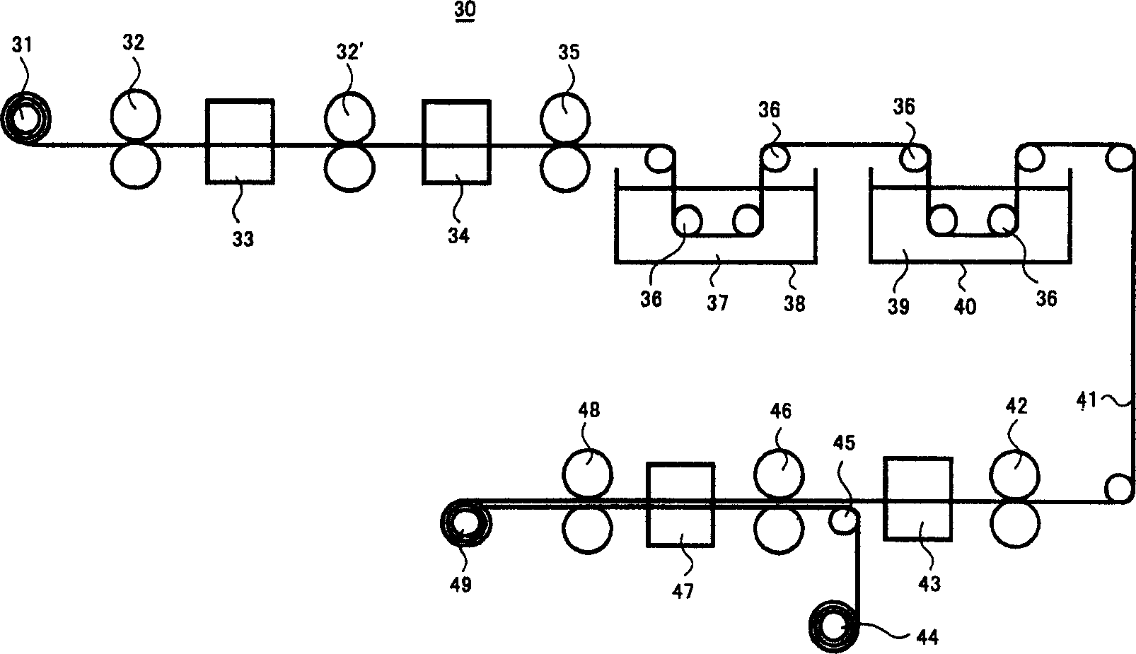
[0132] In Example 2, figure 2 It shows a continuous manufacturing device 20 that uses a polarizing optical element, and deposits aluminum metal on the surface of a polyvinylidene fluoride film by vapor deposition to manufacture a film-like polarizing optical element. First, the polyvinylidene fluoride film supplied from the polyvinylidene fluoride film supply roll 21 is passed through the roll 22, the first constant temperature bath 23 maintained at 60°C, and the roll 22' is stretched 5 times in the axial direction. After that, the tension is continued to be maintained, and a heat treatment is performed for 5 minutes in the second constant temperature bath 24 maintained at 120° C. to crystallize a part of the polyvinylidene fluoride film.

[0133]After that, the aluminum metal was vapor-deposited in a vacuum vapor deposition tank 25 with a thickness of 50 nm, and then passed through a roller 26, a third constant temperature bath 27 maintained at 80°C, and a roller 26' to further ...

Embodiment 3

[0135] In Example 3, silver metal was deposited on the surface of the polypropylene film by electroless plating (electroless plating) to form a polarizing film. First of all. After the polypropylene film was stretched 5 times at 80°C, the tension was continued to be maintained, and a heat treatment was performed at 110°C for 10 minutes to crystallize a part of the polypropylene film. After the film is chlorinated through the first tin solution, it is gently rinsed with water. The amorphous part where the first tin chloride passed through the ammoniated silver nitrate solution is selectively adsorbed is only electrolessly plated to meet the uneven precipitation on the film surface Silver metal. The polarization performance of the obtained polarizing film showed a value of extinction ratio of 1:5000 in the visible light region of 420 nm to 700 nm. The light transmittance is 48%.

[0136] In addition, this Example 3 shows an example of using silver as the electroless plating layer. H...


PUM

PropertyMeasurementUnit
wavelengthaaaaaaaaaa
reflectivityaaaaaaaaaa

Abstract

The invention provides a grid-type polarizing optical element which can be used in the visible light region to the infrared light region, its continuous manufacturing method and the polarizing optical element. The polypropylene film is stretched 4 times in the axial direction by roller (12), the first constant temperature tank (13), and roller (12`), after which aluminum metal is vapor-deposited to 10 nanometers in the vacuum vapor deposition tank (14). The thickness, and then, in roll (15), the 2nd constant temperature bath (16), roll (15 ') carry out 2 times stretching along axial direction simultaneously with polypropylene film part crystallization. At this time, the aluminum metal forms homogeneous cracks in a direction perpendicular to the stretching direction. After that, the film was heat-treated in a third constant temperature bath (17), and then wound up on a winding roll (18). The obtained film-shaped polarizing optical element had a polarization rate of 99.5% and a light transmittance of 90% in the infrared wavelength range of 1 micrometer to 10 micrometers. In addition, the reflectance of infrared rays measured at a place perpendicular to the film was 99.9% or more.

Description

Technical field [0001] The present invention relates to a polarizing optical element, a manufacturing method thereof, and a reflective optical element using the element, in particular to the control of a high-order polymer structure, from several nanometers to several tens of nanometers, with a length of several tens of nanometers to several millimeters. A grid-type polarizing optical element that can be used in the visible light region to the infrared region and a continuous manufacturing method thereof with an anisotropic conductive material formed on its surface or inside, and a reflective optical element using the polarizing optical element. Background technique [0002] Up to now, people have known three methods for making thin-film polarizing optical elements. The first method is a method of doping a stretched polyvinyl alcohol (PVA) film with a dichroic dye such as iodine as disclosed in Patent Document 1 below. In this method, a thin film of PVA with a dichroic substance ...

Claims


Application Information

Patent Timeline
Patent Type & Authority Applications(China)
IPC IPC(8): C08J5/18G02B1/11G02B5/30G02F1/1333
CPCC08J5/18G02B5/3058G02B5/3033G02F1/133528
Inventor 宫田清藏
Owner 宫田 清藏
Learn More