

Bioreactor for treating wastewater
A bioreactor and waste water treatment technology, which is applied in the field of environmental bioengineering, can solve the problems of large land occupation, low efficiency, and high cost of biological treatment facilities, so as to improve the ability to withstand high loads, improve mass transfer efficiency, and reduce load shocks Effect
- Summary
- Abstract
- Description
- Claims
- Application Information
AI Technical Summary
Problems solved by technology
Method used
Image

Examples
Embodiment 1
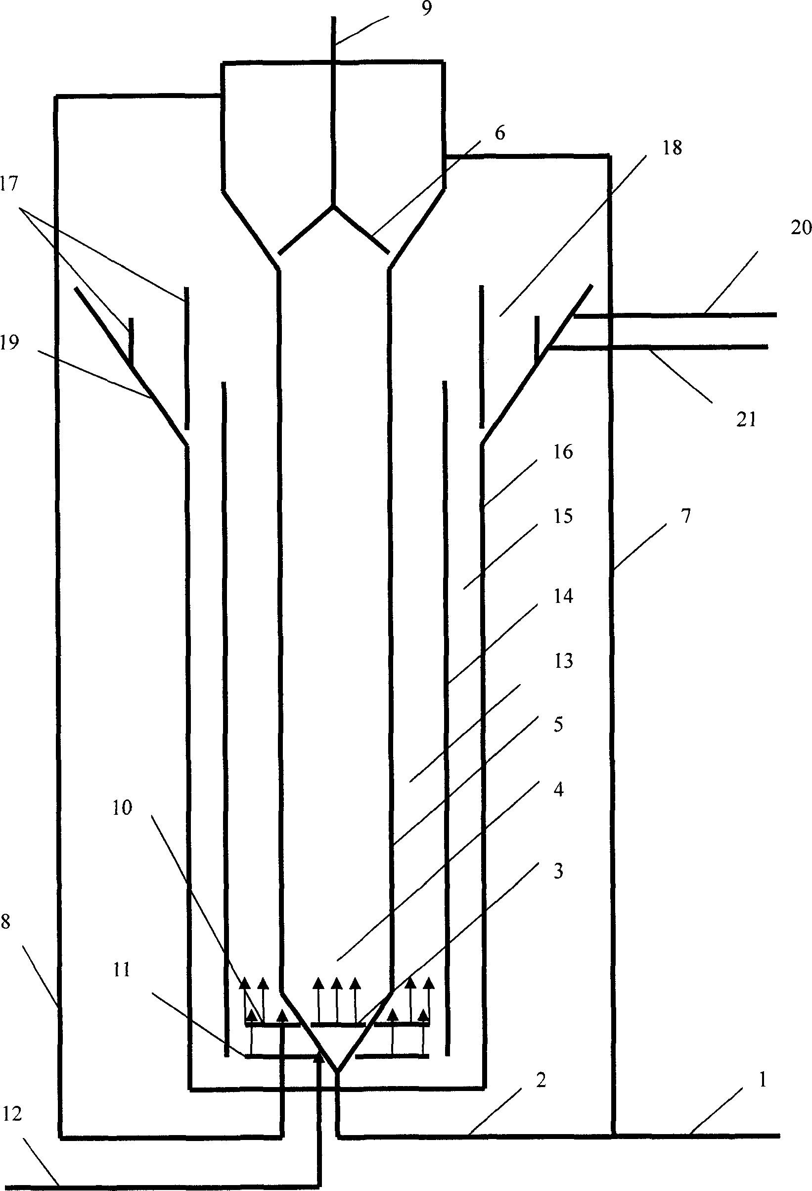
[0022] Example 1: The total effective volume of the reactor is 25.15L, of which the effective volume of the anaerobic zone of the reactor is 8.15L, the anaerobic zone is φ90mm, h1495mm; An outlet pipe and a return pipe are respectively set above the three-phase separator, and the anaerobic outlet water is connected to the aerobic zone for subsequent treatment, and the operation mode of backflow or non-backflow can be selected according to the needs of the treated water quality. The effective volume of the aerobic zone is 15L, the upflow zone of the aerobic zone is φ150mm, and the height is 1125mm; the downflow zone of the aerobic zone is φ200mm, and the height is 1015mm. The aerobic area is equipped with perforated water distributors and air distribution pipes. The settlement zone is an inverted cone.
Embodiment 2
[0023]Embodiment 2: The reactor described in Embodiment 1 is adopted, the influent is glucose water, the influent COD is 3000-5000mg / L, the treated water is 30-50L / d, and the anaerobic-aerobic biological treatment process is adopted. When the reactor is started, the anaerobic zone is inoculated with anaerobic granular sludge, and the aerobic zone is not inoculated with sludge, but uses microbial agent TR-20 and a polymer composite carrier developed by itself (patent has been declared) to form biological particles. Operating at room temperature (about 25°C), the total organic load of the reactor reaches 6.5kgCOD / m3d, of which the organic load in the anaerobic zone can reach 18.4kgCOD / m3d, and the organic load in the aerobic zone can reach 2.0kgCOD / m3d. The COD removal rate of the reactor reaches over 90%. Operating at a medium temperature (about 30°C), the total organic load of the reactor reaches 10kgCOD / m3d, of which the organic load in the anaerobic zone reaches more than 29...
Embodiment 3
[0024] Embodiment 3: Using the reactor described in Embodiment 1, the influent is a low carbon source and high ammonia nitrogen distribution water, the influent COD is about 200mg / L, NH4+-N600-700mg / L, and the anaerobic area is inoculated with anaerobic particles when the reactor is started Sludge and bacterial agent B-350, aerobic zone inoculation bacterial agent B-350 and self-developed polymer composite carrier (patent declared) form biological particles. The aerobic-anaerobic biological treatment process is adopted. The influent water enters the aerobic zone first, and the aerobic nitrification reaction is carried out first, and the dissolved oxygen concentration, pH, ammonia nitrogen load and hydraulic retention time are controlled to make the aerobic nitrification reaction proceed until the ammonia nitrogen is converted into sub- The conversion rate of nitrate nitrogen is about 50%. The aerobic treatment effluent is then pumped into the anaerobic zone for anaerobic ammoni...
PUM
 Abstract
Description
Claims
Application Information