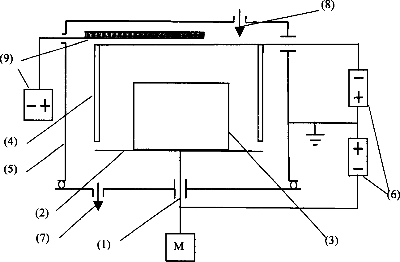
Thermal electron reinforced ionic boronizing device and process
A hot electron and ion infiltration technology, applied in the field of ion boronizing, to achieve the effect of expanding the working pressure range, increasing the infiltration speed, and strong operability
- Summary
- Abstract
- Description
- Claims
- Application Information
AI Technical Summary
Problems solved by technology
Method used
Image
Examples
Embodiment approach 1
[0020] As shown in the attached picture. Place a steel workpiece 3 with a size of 40mm×20mm (diameter×height) on a steel cathode tray 2 with a size of 80mm (diameter), and hang 6 pieces of steel with a size of 25mm×15mm×5mm (length×width×thickness) around it. The source electrode 4 of the iron-boron strip ensures that the distance between the iron-boron strips and between the iron-boron strip and the workpiece is 10cm-25cm. Vacuum up to 10 -1 After Pa, fill in argon gas to 50Pa, apply a voltage of -500V between the workpiece 3 and the vacuum container 5, and apply a voltage of -1000V between the workpiece 3 and the vacuum container 5, and apply a voltage of -1000V between the iron boron source electrode 4 and the vacuum container 5, and wait for the temperature of the workpiece to rise to 850°C. Keep warm for 2 hours, drop to room temperature, take out the sample out of the oven. The thickness of the boronizing layer on the surface of 45 steel workpiece is 0.03mm, and the su...
Embodiment approach 2
[0022] Furnace loading is the same as embodiment 1. The workpiece 3 is made of Ti6Al4V alloy, and the source 4 is made of boron iron. Vacuum up to 10 -1 After Pa, fill in argon gas to 50Pa, apply a voltage of -400V between the workpiece 3 and the vacuum container 5, and apply a voltage of -800V between the iron boron source 4 and the vacuum container 5, ignite the thermionic emission device, and reduce The pressure in the furnace is reduced to 3Pa, when the temperature of the workpiece is raised to 800°C, keep it warm for 2 hours, then drop to room temperature, and take out the sample from the furnace. The thickness of boron-iron co-infiltration layer on the surface of Ti6Al4V alloy workpiece is 0.01mm, and the surface hardness reaches 1100HV.
Embodiment approach 3
[0024] Furnace loading is the same as embodiment 1. The workpiece 3 is made of 20 steel, and the source 4 is made of boron nickel. Vacuum up to 10 -1 After Pa, fill in argon gas to 50Pa, apply a voltage of -600V between the workpiece 3 and the vacuum container 5, and apply a voltage of -1200V between the iron boron source electrode 4 and the vacuum container 5, ignite the thermionic emission device, and reduce The pressure in the furnace is reduced to 3Pa. When the temperature of the workpiece is raised to 950°C, the temperature is kept for 2 hours, and then it is lowered to room temperature, and the sample is taken out of the furnace. The thickness of the boron-iron co-infiltration layer on the surface of 20 steel workpiece is 0.04mm, and the surface hardness reaches 1000HV.
PUM
 Abstract
Description
Claims
Application Information
 - R&D
- Intellectual Property
- Life Sciences
- Materials
- Tech Scout
- Unparalleled Data Quality
- Higher Quality Content
- 60% Fewer Hallucinations
Browse by: Latest US Patents, China's latest patents, Technical Efficacy Thesaurus, Application Domain, Technology Topic, Popular Technical Reports.
© 2025 PatSnap. All rights reserved.Legal|Privacy policy|Modern Slavery Act Transparency Statement|Sitemap|About US| Contact US: help@patsnap.com

