High precision tunnel type accelerometer and preparation method thereof

An accelerometer, tunnel-type technology, applied in the direction of using inertial force for acceleration measurement, etc., can solve the problems of difficult control of the height and initial spacing of the tunnel tip, rapid corrosion of lobes, and complicated processes, so as to avoid adhesion and tunnel tip. The effect of contamination, improved measurement accuracy, and improved sensitivity

Inactive Publication Date: 2005-07-06
PEKING UNIV
View PDF0 Cites 19 Cited by
  • Summary
  • Abstract
  • Description
  • Claims
  • Application Information

AI Technical Summary

Problems solved by technology

They use a combination of surface technology and KOH wet etching process, and perform discrete packaging after dicing, which achieves high precision, but the process is complicated, and it loses the unique batch advantages of MEMS technology, making it difficult to manufacture in large quantities. Poor performance (Cheng-Hsien Liu and Thomas W. Kenny A high-precision, wide-bandwidth micromachined tunneling accelerometer, Journal of Microelectromechanical Systems, vol.10, No.3, September 2001 pp425-433)
Khalil Najafi and others at the University of Michigan in the United States studied the use of concentrated boron diffusion technology to prepare tunnel accelerometers, but due to internal stress and other problems caused by concentrated boron diffusion, they failed to successfully process high-precision tunnel accelerometers (Chingwen Yeh and Khalil Najafi, A Low-Voltage Tunneling-Based Silicon Microaccelerometer IEEE TRANSACTIONS ON ELECTRONDEVICES, VOL.44, NO.11, NOVEMBER 1997 pp1875-1882)
The current method of preparing the tunnel tip is basically obtained by KOH etching, but due to the rapid corrosion of the convex corner, the height and initial spacing of the tunnel tip are not easy to control

Method used


Image

  • High precision tunnel type accelerometer and preparation method thereof
  • High precision tunnel type accelerometer and preparation method thereof
  • High precision tunnel type accelerometer and preparation method thereof

Examples


Embodiment 1

[0028] Embodiment 1: High precision tunnel accelerometer structure

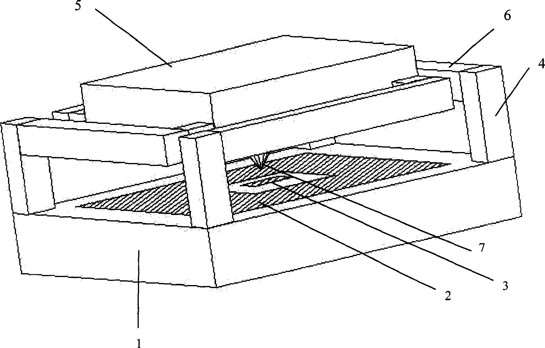
[0029] Such as figure 1 Shown is a schematic diagram of a high-precision tunnel accelerometer. It includes a glass substrate 1, on which there are driving electrodes 2 and tunnel tip corresponding electrodes 3, and the glass substrate 1 is fixedly connected to the rotary support beam 6 distributed around the detection mass 5 through anchor points 4, and the detection mass 5 It is fixedly connected with the support beam 6 , the tunnel tip 7 is located under the center of the proof mass 5 , the tunnel tip 7 is conical, and the thickness of the support beam 6 is smaller than that of the proof mass 5 .

Embodiment 2

[0030] Embodiment 2: the preparation method of high precision tunnel accelerometer

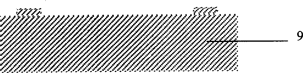
[0031] Figure 2 shows the fabrication process of the high-precision tunnel accelerometer.

[0032] 1. The starting material is a double-polished N-type (100) silicon wafer 9 with a thickness of 400±10 microns;

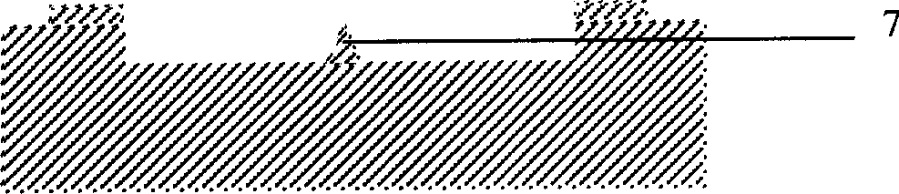
[0033] 2. KOH corrosion, prepare the initial distance between the tunnel tip and the corresponding electrode, as shown in Figure 2(a), the depth of the shallow groove is the initial distance;

[0034] 3. HNA isotropically etched to prepare the tunnel tip 7, as shown in Figure 2(b);

[0035] 4. Lift-off process, deposit metal Ti / Pt / Au or Cr / Au on the tunnel tip as the tunnel current emitter electrode 8, as shown in Figure 2(c);

[0036] 5. Lift-off process, prepare the substrate electrode on the glass substrate 1, including the driving electrode 2 and the tunnel tip corresponding electrode 3, the electrode is Ti / Pt / Au or Cr / Au, as shown in Figure 2(d);

[0037] 6. Anode bonding, real...


PUM


Abstract

This invention provides a high accurate tunnel accelerometer structure and its process method, which comprises the following steps: first etching on the silicon pad and determining the initial distance between tunnel head to the electrode; keeping etching the tunnel head and depositing metal on the head as tunnel current emission electrode; processing drive electrode and tunnel head electrode on the glass underlay; positive electrode bonding to realize the underlay and silicon pad alignment and sticking; etching the silicon back with dry deep groove etching process to generate supportive beam; keeping etching silicon pad back to generate mass block and releasing structure to get the accelerometer.

Description

Technical field: [0001] The invention belongs to the field of micro-electromechanical system processing, and relates to a structure of a high-precision tunnel accelerometer and a preparation method thereof. Background technique: [0002] As an emerging high-tech field, micro-electro-mechanical systems (MEMS) use advanced semiconductor technology to integrate the entire mechanical structure into a chip, and have been widely used in military, biomedical, automotive and other industries. These devices are mainly processed into various structures based on silicon materials. In recent years, the gradual maturity of dry deep groove etching technology has provided a basic technical reserve for the development of high-precision, new-principle MEMS devices. [0003] High-precision tunnel accelerometer is a new type of device based on quantum tunneling effect. In 1986, American scientist G.BinnigH.Rohrer and others won the Nobel Prize in Physics for designing and developing a scannin...

Claims


Application Information

Patent Timeline
Patent Type & Authority Applications(China)
IPC IPC(8): G01P15/08
Inventor 董海峰贾玉斌郝一龙
Owner PEKING UNIV
Why Eureka
Try Eureka