
Catalyst for removing nitrogen oxides, method for production thereof and method for removing nitrogen oxides

A technology of nitrogen oxides and catalysts, which is applied in the field of catalysts and can solve problems such as catalyst degradation and high catalyst manufacturing costs

Inactive Publication Date: 2005-07-20
MITSUBISHI HITACHIPOWER SYST LTD
View PDF2 Cites 15 Cited by
  • Summary
  • Abstract
  • Description
  • Claims
  • Application Information

AI Technical Summary

Problems solved by technology

Therefore, one disadvantage of the co-precipitation method is the high cost of catalyst manufacture
[0007] In addition, in the method in which Ce ions are highly dispersed in the microvoids of zeolite, although a catalyst with extremely high initial performance can be obtained, the catalyst is easily deteriorated by the so-called dealumination phenomenon in which the The aluminum contained in the zeolite is separated from the zeolite structure into the microvoids of the zeolite

Method used


Image

  • Catalyst for removing nitrogen oxides, method for production thereof and method for removing nitrogen oxides
  • Catalyst for removing nitrogen oxides, method for production thereof and method for removing nitrogen oxides
  • Catalyst for removing nitrogen oxides, method for production thereof and method for removing nitrogen oxides

Examples


Embodiment 1

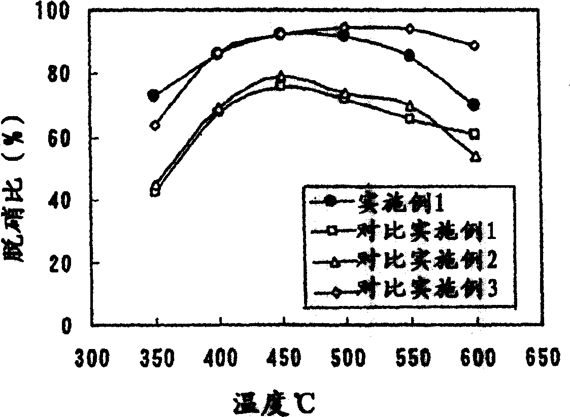
[0045] 80 g of titanium dioxide dried at low temperature (produced by Millennium Co., Ltd., trade name: G5, surface area 275m 2 / g), 52.7g ammonium metatungstate aqueous solution ((NH 4 ) 6 ·H 2 W 12 o 40 ·xH 2 O, the concentration in the solution is expressed as WO 3 Calculated as 50wt%), 26.2g CeO 2 Sol (produced by Taki Chemical Co., Ltd., trade name: Needrahl, CeO 2 Content: 15wt%), 4g oxalic acid, 50g silica sol (produced by Nissan Chemical Ind., trade name: OS sol, concentration: 20wt%) and 50g water mix, prepare TiO 2 Catalyst slurry with a concentration of 30 wt%.

[0046] A corrugated honeycomb made of aluminosilicate type inorganic fibers (produced by Nichias Co., Ltd., trade name: No. 3722) was cut into 5 cm squares, and immersed in the catalyst slurry thus obtained so that the catalyst slurry It was supported between inorganic fibers and on the surface of the fibers, dried at 150° C., and then calcined at 600° C. for 2 hours to prepare a catalyst.

[0047...

Embodiment 2 and 3

[0049] Catalyst is prepared in the same way as in Example 1, except that ammonium metatungstate aqueous solution and CeO 2 The addition amount of sol changes to 83.8g and 27.6g (embodiment 2) respectively, or 24.9g and 24.8g (embodiment 3), but in two embodiments by adjusting the addition amount of water to make the TiO of catalyst slurry 2 The concentration was maintained at about 30 wt%.

[0050] The chemical compositions of the catalysts thus obtained are respectively Ti / W / Ce (83 / 15 / 2 (Example 2) and 93 / 5 / 2 (Example 3)), in atomic percent.

Embodiment 4 to 6

[0052] Catalyst is prepared in the same way as in Example 1, except that ammonium metatungstate aqueous solution and CeO 2 The addition amount of sol changes to 52.1g and 12.9g (embodiment 4) respectively, 53.3g and 39.7g (embodiment 5), or 54.9g and 67.8g (embodiment 6), but in each embodiment by adjusting water The amount of addition makes the TiO of the catalyst slurry 2 The concentration was maintained at about 30 wt%.

[0053] The chemical compositions of the catalysts thus obtained are respectively Ti / W / Ce (89 / 10 / 1 (Example 4), 87 / 10 / 3 (Example 5), and 85 / 10 / 5 (Example 6)), In atomic percent.


PUM


Abstract

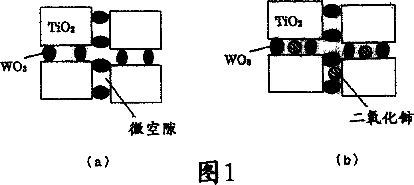
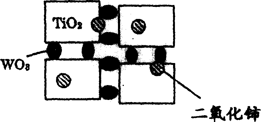
Disclosed is a method for producing a catalyst for removing nitrogen oxides which comprises dispersing a hydrated titanium (Ti) oxide or dried material thereof, tungstic acid or a salt thereof, and cerium (Ce) dioxide in a dispersion medium to form a sol-like material, mixing the sol-like material with an aqueous medium to form a catalyst slurry or paste, supporting the catalyst slurry or paste on a catalyst carrier, and then calcinating the carrier; in which catalyst the Ce dioxide is prevented from being embedded in the Ti oxide to realize such a high degree of dispersion of the Ce dioxide on the surface of the Ti oxide as comparable with the case wherein cerium ions are dispersed in micro voids of a zeolite by ion exchange; and the catalyst is free from the occurrence of such phenomena as sintering of the Ti oxide, and deterioration of zeolite with steam when a zeolite is used as carrier.

Description

technical field [0001] The invention relates to a method for removing nitrogen oxides (NOx) contained in exhaust gas X ) catalyst, preparation method of said catalyst and removal of NO X Methods. More specifically, the present invention relates to a method for removing NO contained in exhaust gas at a temperature above 450°C X Catalyst, preparation method of said catalyst and removal of NO contained in exhaust gas X Methods. Background technique [0002] In countries such as the United States, which consumes a large amount of electric power, power generation using so-called simple-cycle gas turbines, which are installed and operated separately, has been increasing to supplement power and cope with peak periods of power consumption. Since the equipment used for power generation is installed on the outskirts of towns, a high proportion of NO contained in the exhaust gas must be X decomposed to purify the gas. On the other hand, in power generation using simple cycle gas ...

Claims


Application Information

Patent Timeline
Patent Type & Authority Applications(China)
IPC IPC(8): F01N3/08B01D53/86B01D53/94B01J21/06B01J23/10B01J23/30B01J37/02
CPCB01J37/0215B01D2255/20707B01D2255/2065B01D2251/2062B01J23/30B01D2255/50B01D53/8628B01D53/9418B01D2255/20776B01J23/10B01J21/063B01J37/02B01D53/94F01N3/08
Inventor 加藤泰良今田尚美永井良宪
Owner MITSUBISHI HITACHIPOWER SYST LTD
Learn More