
Synchronous sintering process for electronic beam selection zone and three dimension layered producing device

A three-dimensional layering, manufacturing equipment technology, applied in electron beam welding equipment, metal processing equipment, manufacturing tools, etc., can solve the problem of low efficiency, can only be sintered and deposited point by point or partition, and can only be sintered and deposited point by point or partition. Heating etc.

Active Publication Date: 2005-08-03
TSINGHUA UNIV
View PDF0 Cites 82 Cited by
  • Summary
  • Abstract
  • Description
  • Claims
  • Application Information

AI Technical Summary

Problems solved by technology

Due to the limitations of energy density and material sintering characteristics, in order to complete the sintering deposition of the material in one scan, the scanning speed of the electron beam or laser is limited, and the material powder can only be heated point by point or partition. Points or partitions are deposited by sintering
Therefore, the uniformity of heating is less, and the efficiency is lower

Method used


Image

  • Synchronous sintering process for electronic beam selection zone and three dimension layered producing device
  • Synchronous sintering process for electronic beam selection zone and three dimension layered producing device
  • Synchronous sintering process for electronic beam selection zone and three dimension layered producing device

Examples


Embodiment Construction

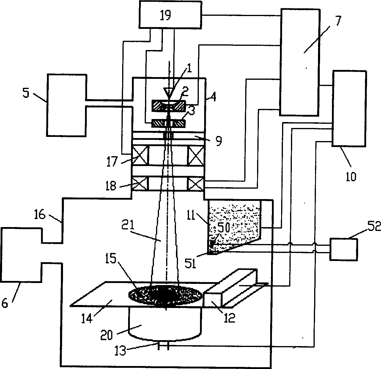
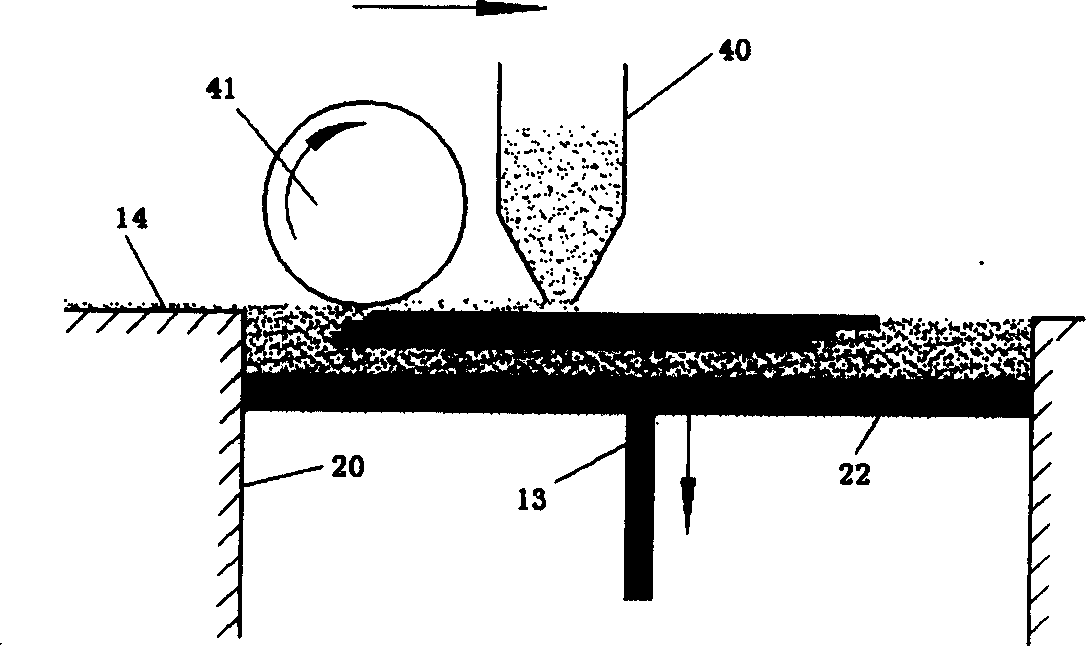
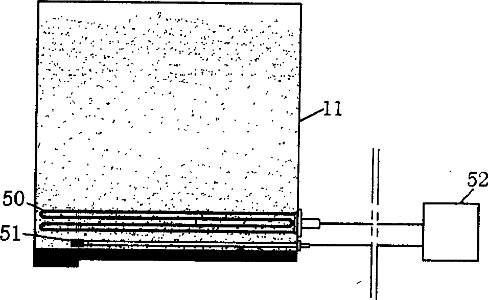
[0027]The three-dimensional layered manufacturing equipment provided by the present invention mainly includes the following parts: a powder spreading platform 14, which is used to constrain the powder in the powder spreading process; After the piston falls to a preset height relative to the powder spreading platform, a narrow space with a set height is formed on the upper part of the forming cylinder; the height of the space is equal to the thickness of the layer to be constructed; the powder spreading and pressing device 12 is located at On the powder spreading platform, the powder spreading platform can be swept horizontally to fill the carried powder in the upper space of the molding cylinder and flatten and compact it, and send the excess powder to the residual material recovery device; the powder supply device 11, It is installed above the powder spreading platform for storing and supplying powder; the powder recovery device is suspended at both ends of the powder spreadin...


PUM


Abstract

The present invention relates to technology and apparatus with high energy beam to sinter or melt and deposit material successively to realize laminated solid manufacture. The present invention features that the electronic beam scan controller controls the electronic beam to scan fast in pattern projection mode for heating powder homogeneously. Each scanning of the electronic beam has short time in the selected area, so that the scan initiating point has no great temperature change generated during the whole scanning course. Through one or several frames of scanning, the material in the forming area has temperature synchronously raised to reach the sintering or re-melting temperature for deposition onto the forming area before synchronous cooling. The present invention has greatly reduced heat stress and raised forming precision and quality.

Description

technical field [0001] The invention relates to a technique and a device for realizing layered entity manufacturing by sintering or melting and depositing materials layer by layer by using high-energy beams. Background technique [0002] The layered manufacturing of parts or called rapid prototyping is an effective method to solve the fast and low-cost manufacturing of single-piece and small-batch functional parts. The current main process is to use high-energy laser beams or electron beams to scan point by point and layer by layer to melt metal particles and accumulate them into shapes. The specific methods are two kinds of selective sintering and cladding. Typical processes are laser selective sintering (Journal of Materials Processing Technology, 2003, 141(1)) and laser engineered near-forming (Proceedings of The 10th Solid Freeform Fabrication Symposium, University of Texas Austin, August 9-11, 1999). As well as electron beam melting (Rapid Prototyping Journal, 2004 10...

Claims


Application Information

Patent Timeline
IPC IPC(8): B22F3/105B23K15/02G05B15/02G05B19/19
Inventor 林峰颜永年闫占功齐海波
Owner TSINGHUA UNIV
Learn More