
Hazardous waste treatment method and apparatus

A waste treatment, waste treatment system technology, applied in the field of industrial waste gas treatment or hazardous waste treatment system

Inactive Publication Date: 2005-08-10
刘健安 +1
View PDF0 Cites 21 Cited by
  • Summary
  • Abstract
  • Description
  • Claims
  • Application Information

AI Technical Summary

Problems solved by technology

However, increasing the residence time requires using a larger unit or reducing the amount of waste added

Method used


Image

  • Hazardous waste treatment method and apparatus
  • Hazardous waste treatment method and apparatus
  • Hazardous waste treatment method and apparatus

Examples


Embodiment Construction

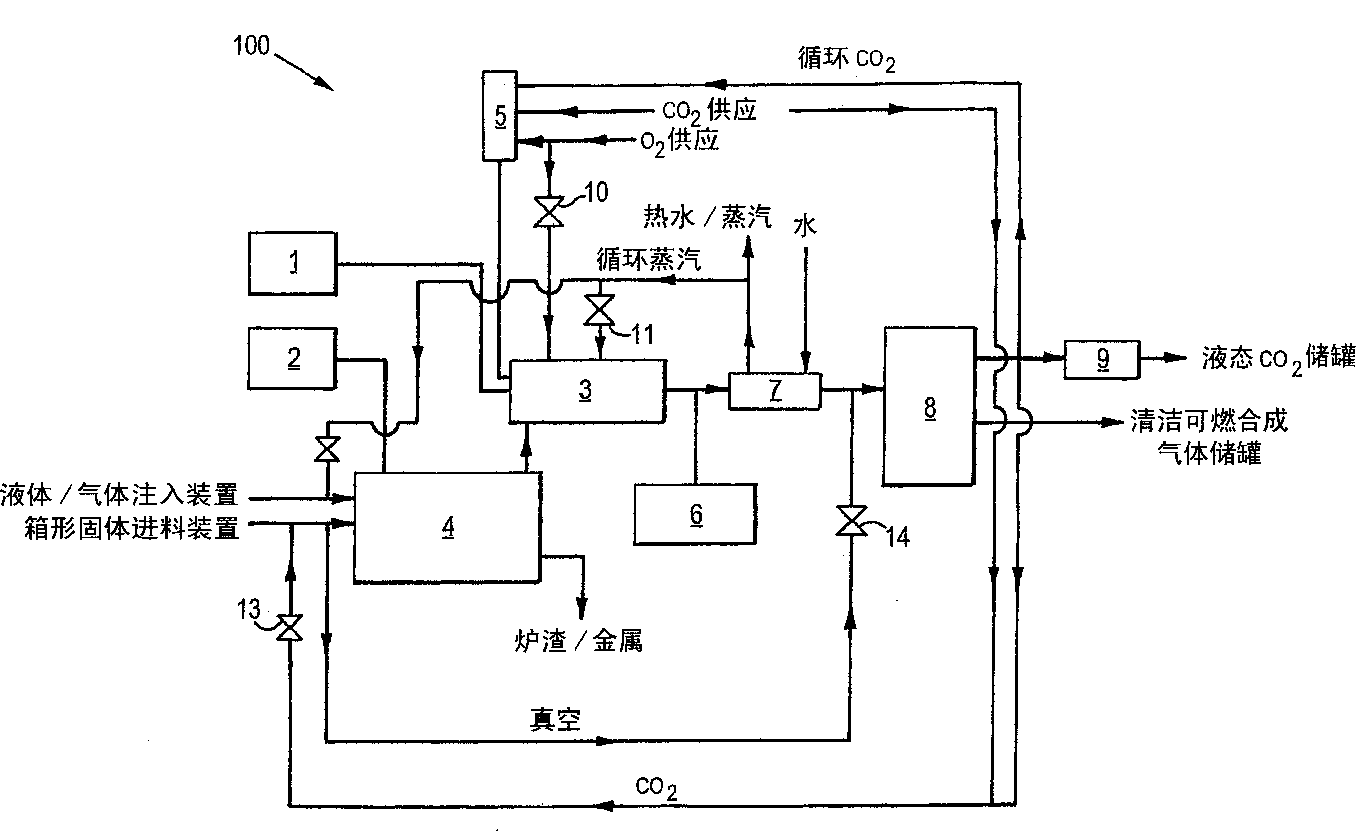
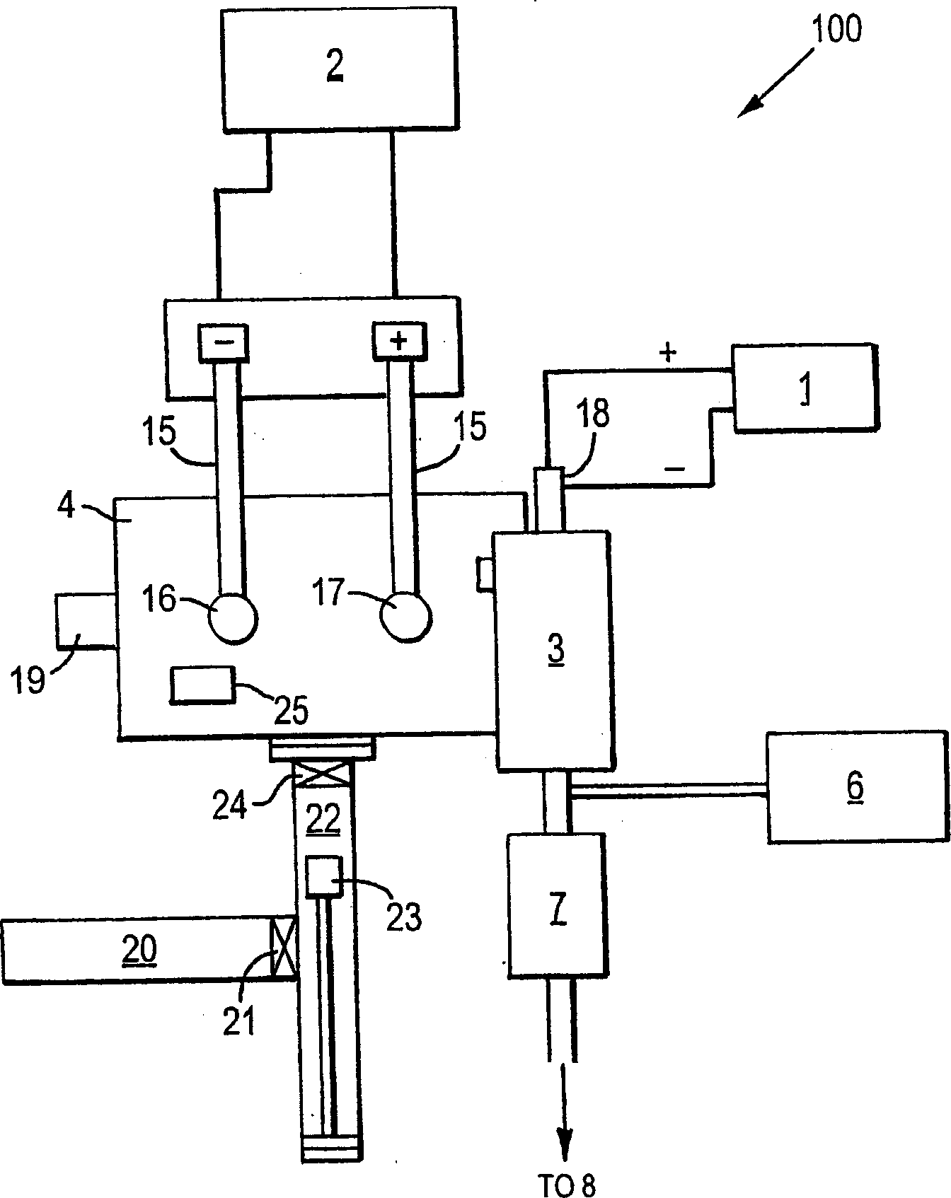
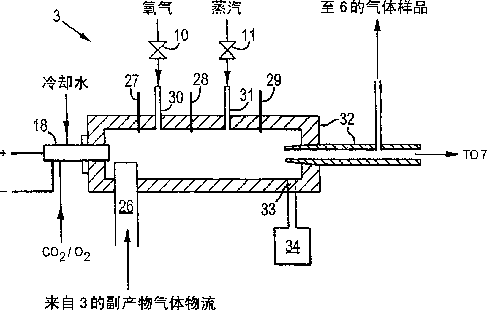
[0023] first reference figure 1 and figure 2 , figure 1 shows a diagram of the waste treatment system 100 of the present invention, while figure 2 A top down block diagram of waste treatment system 100 is shown. System 100 includes graphite electrode D.C. plasma arc gasifier / melter 4 and plasma torch cyclone oxidizer 3 . The waste material is introduced into the gasifier / melter 4 which melts the non-combustible material and decomposes the organic material. The off-gas from the gasifier / melter 4 is introduced into the cyclone oxidizer 3 . The cyclone oxidizer 3 then treats the exhaust gas according to the invention. The gasifier / melter 4 can also be considered a gasification / vitrification chamber.

[0024] The gasifier / melter 4 is preheated to above 1500°C by molten scrap steel in the gasifier / melter 4 before filling the hazardous waste into the gasifier / melter 4 of the graphite electrode D.C. arc for destruction temperature. The gasifier / melter 4 is refractory lined ...


PUM


Abstract

A synthetic gas production system from high heating value wastes is disclosed. The system comprises a primary waste treatment stage to receive the high heating value wastes and produce a by-product off-gas; and a secondary waste treatment stage coupled to said primary waste treatment stage to receive the by-product off-gas. The secondary waste treatment stage includes a refractory-lined cylindrical chamber having an input port for tangentially receiving said by-product off-gas and an output port. It also includes a DC powered plasma torch proximate the input port within the chamber, the torch receiving a nitrogen-free working as including a mixture of carbon dioxide and oxygen. The plasma torch heats the chamber and the by-product off-gas is converted a synthetic gas, which is ejected through the output port. An oxygen injector and a steam injector is in communication with said refractory-lined cylindrical chamber secondary treatment stage for atomized oxygen and atomized steam injections and a sensor is coupled to said output port of said refractory-lined cylindrical chamber for measuring temperature of said refractory-lined cylindrical chamber and analyzing the content of said synthetic gas. A process controller is coupled to said sensor for receiving data from said sensor and coupled to the injectors for controlling the injection of oxygen and steam.

Description

[0001] Cross References to Related Applications [0002] This application claims priority to US Provisional Patent Application Serial No. 60 / 378,357, filed May 8, 2002, the disclosure of which is hereby incorporated herein. technical field [0003] The invention relates to a system for treating industrial waste gas or hazardous waste. Background technique [0004] In addition to being a serious source of pollution, hazardous waste also affects human health through its toxicity, flammability, corrosion, reactivity and infectivity. Hazardous waste is usually disposed of through land disposal, incineration and recycling. However, as some inappropriate waste disposal events such as waste incineration and release of toxic substances in landfills (such as dioxins from incineration and toxic leachates from landfills) started to create serious health and ecological problems, the public The concern has led to increased legislation and stricter environmental protection policies. Th...

Claims


Application Information

Patent Timeline
IPC IPC(8): F23G5/00B01D53/32B01D53/70B01J4/00B01J19/08B09B3/00C02F1/00C10J3/18F23G5/08F23G7/06
CPCF23G5/085C10J2300/0973Y02E20/12C10J2300/1634C10J2300/1238B01D53/32C10J2300/0969C10J2300/1693F23G7/063C10J2300/1884F23G7/061C10J3/18C10J2300/1892C10J2300/0959F23G2209/14B01J19/08F23G5/08F23G7/06
Inventor 陈振邦
Owner 刘健安
Learn More