Valve

A technology of valves and discs, applied in the field of switching valves, which can solve the problems of high working pressure thrust, large resistance, and increased difficulty in valve opening and closing, and achieve the effects of small operating torque, reduced rotational torque, and extended service life

Inactive Publication Date: 2005-08-17
金庆明
View PDF1 Cites 7 Cited by
  • Summary
  • Abstract
  • Description
  • Claims
  • Application Information

AI Technical Summary

Problems solved by technology

After completing the opening and closing process of the valve, since the seal is not in contact with the ball, the torque to open and close the valve is small, but this structure is not suitable for working under higher pressure or larger caliber, because when the valve is about to open and close In the normal state, the valve disc of the ball valve bears a relatively large working pressure thrust of the medium. Take DN100 as an example: the diameter is 100mm. When the working pressure is 1.0MPa, the thrust of the ball is about 8000N. The structure composed of the nut and the valve stem is borne, and the necessary sealing specific pressure required between the sealing surface and the disc of the ball valve is also borne by the structure composed of the hinged link plate and the left-handed nut and the valve stem, so that the hinged link plate The structure composed of the left-handed nut and the valve stem needs to overcome a large resistance, which increases the difficulty of opening and closing the valve.

Method used


Image

  • Valve
  • Valve
  • Valve

Examples


Embodiment 1

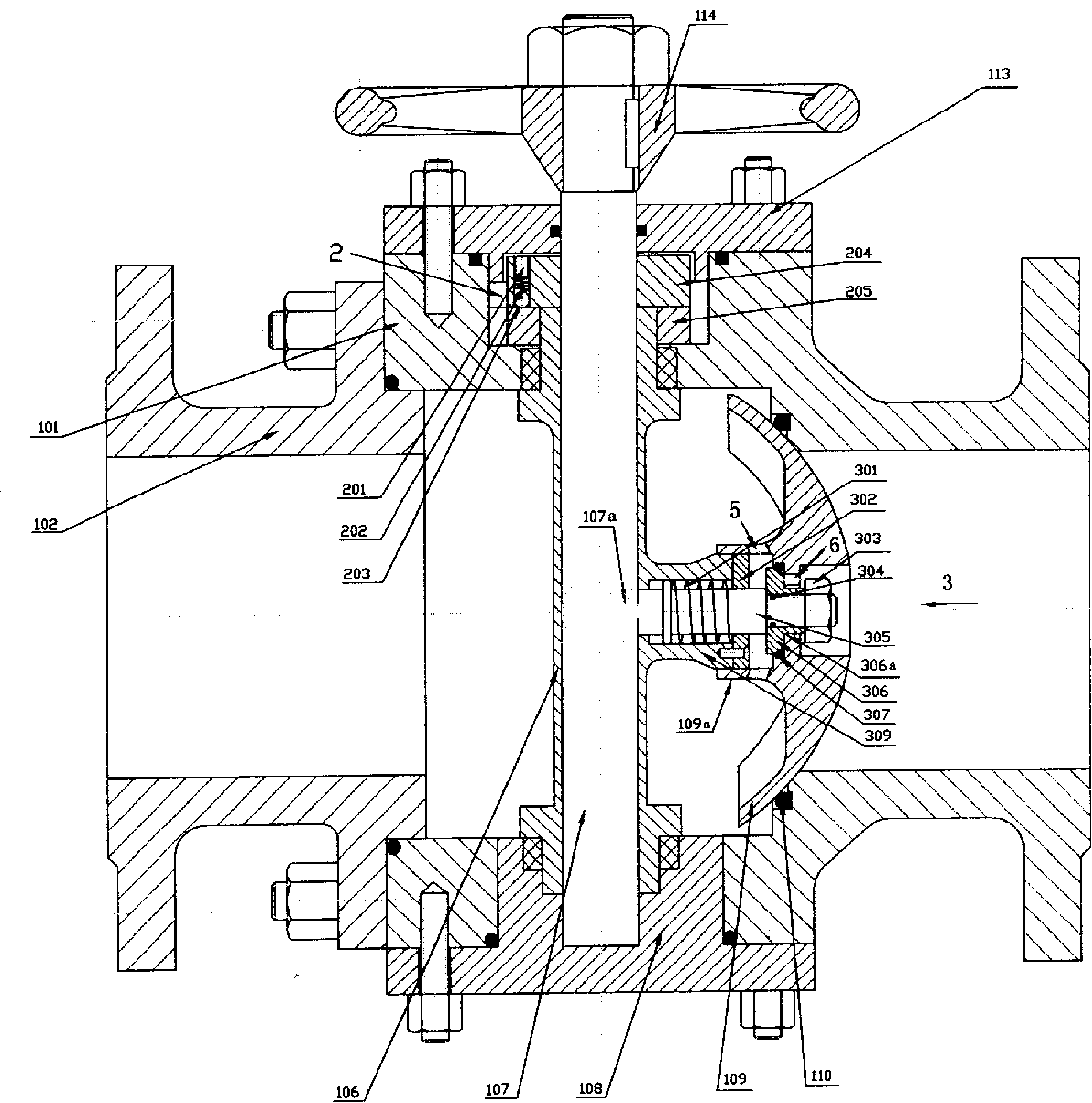
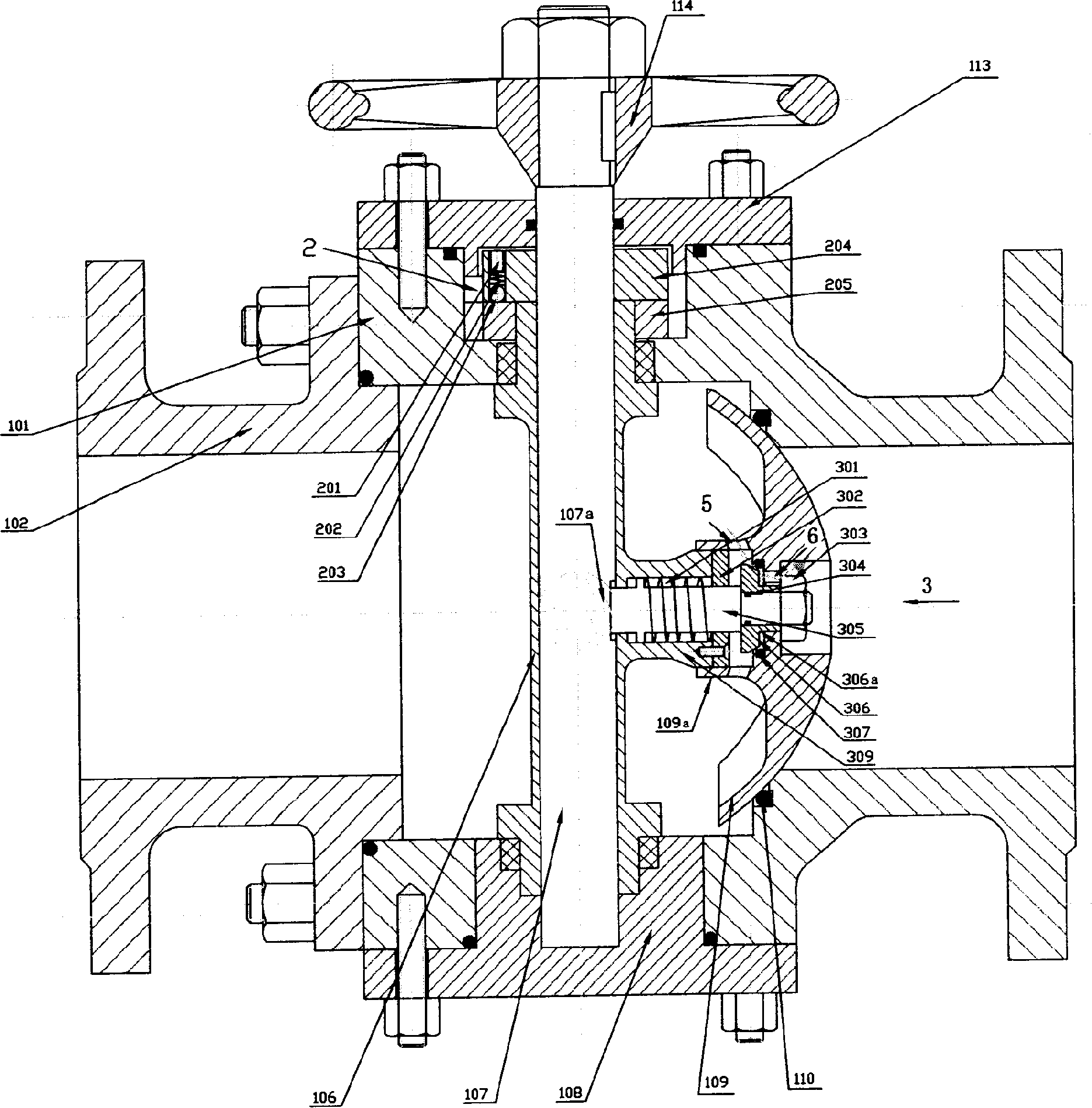
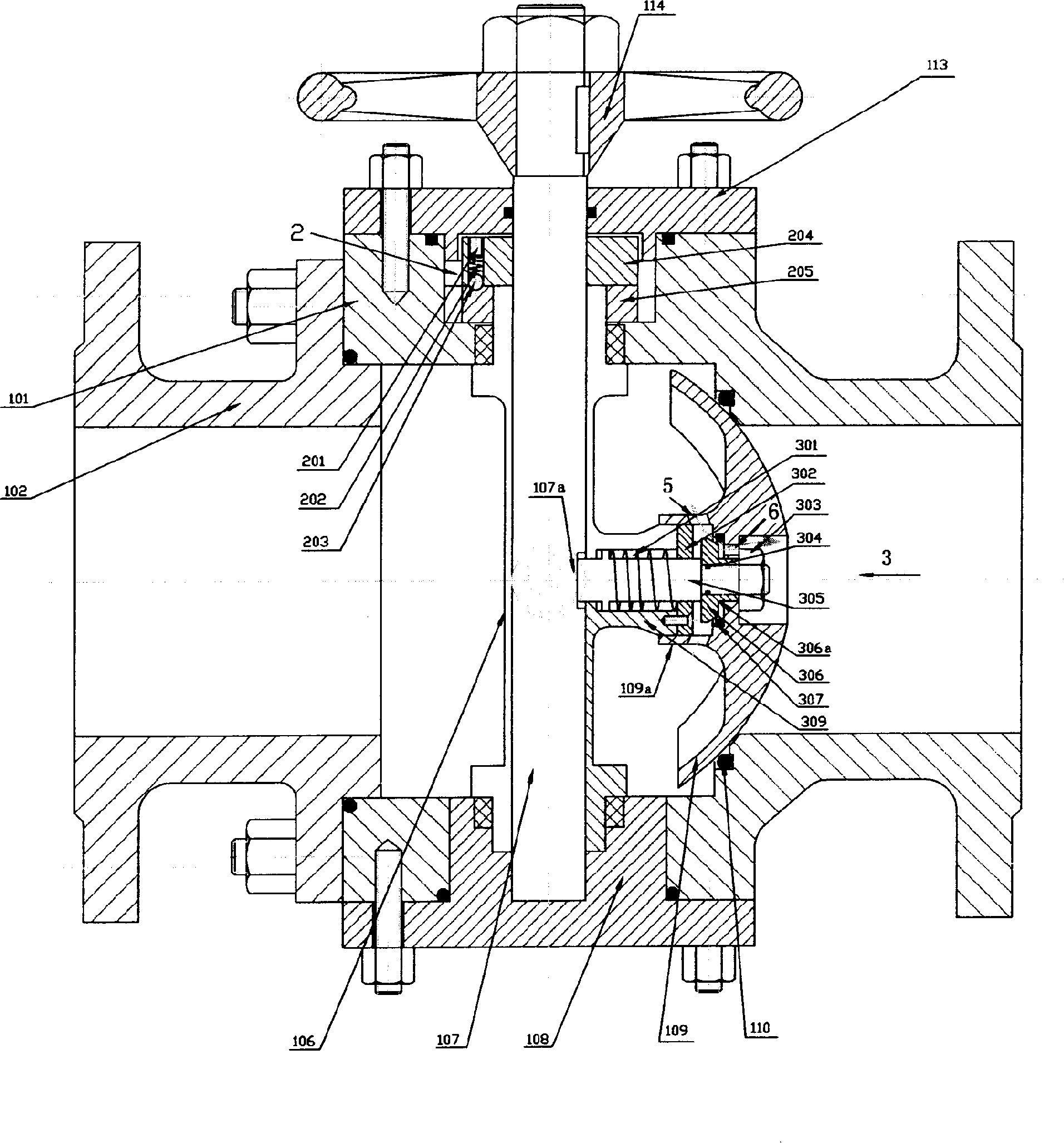
[0018] Such as Figure 1-3 As shown, the valve is mainly composed of a main valve body 101 with upper and lower through holes, a valve disc 109, a valve stem, a handle 114 installed thereon, and an auxiliary mechanism 2. It is characterized in that the valve stem is composed of a drive shaft 107 and The auxiliary driving shaft 106 is composed of a through hole on the auxiliary driving shaft 106, the driving shaft 107 passes through the through hole of the auxiliary driving shaft 106, the valve stem passes through the through hole of the main valve body 101, and an eccentric wheel is arranged on the driving shaft 107 107a (eccentric concave wheel or eccentric cam), a pilot valve body 309 with a through hole is provided on the side of the auxiliary drive shaft 106 corresponding to the eccentric wheel 107a, and a pilot valve body 309 is installed on the pilot valve body 309, so The above-mentioned pilot valve 3 is constituted as follows: the pilot valve rod 305 covered with the s...

Embodiment 2

[0024] Such as Figure 4 As shown, the main difference between this valve and Embodiment 1 is: 1) The auxiliary seal composed of the seal 105 and the left valve disc 103, its main function is to reduce pressure and assist sealing when the pilot valve 3 is opened, not It plays the main sealing role. During the assembly process, the gap between the sealing member 105 and the left valve disc 103 can be adjusted so that the sealing member 105 does not contact the left valve disc 104 to form a gap seal; 2) The actuating mechanism 2 It is constituted like this: a small hole is provided on the auxiliary driving shaft 106 of the through hole on the main valve body 101, a driving wheel 204 installed on the driving shaft 107 is arranged above the auxiliary driving shaft 106, and a driving wheel 204 is arranged on the driving wheel 204. There is a threaded hole that is used to install the screw, and the spring 202 is pressed on the steel ball 203 installed on the threaded hole with the s...


PUM


Abstract

This invention relates to a valve, which comprises main valve with upper and down holes, valve petal, valve bar and handle wheel fixed or electric device and assistant structure. It is characterized by the following: the said valve bar comprises main axis and assistant axis; the valve bar main axis is located with one bias wheel and one guiding valve with hole on one side of the assistant axis; the guiding valve is located with one guiding valve. Due to the guiding valve, the whole valve shall not contact with sealed ring during rotation process to avoid friction force.

Description

technical field [0001] The invention belongs to a low-torque switch valve that can be quickly closed on a pipeline for conveying fluid medium, and is used in industries such as petroleum, chemical industry, light industry, metallurgy, and natural gas. Background technique [0002] At present, ordinary ball valves are generally used as switching valves on pipelines for conveying fluid media. In order to achieve the purpose of sealing, the disc of the ball valve and the seal are always in a state of pressing contact. When the valve is opened and closed, the surface of the seal and the disc of the ball valve There is wear and tear, and leakage will easily occur in the later period of use, and the service life is short. At the same time, the opening and closing torque of the valve is relatively large, and the opening and closing is not flexible. Especially for ball valves with a diameter of Dg80mm and a working pressure above 1.0MPa, it is very difficult to open and close manual...

Claims


Application Information

Patent Timeline
Patent Type & Authority Applications(China)
IPC IPC(8): F16K5/06F16K31/44F16K39/06
Inventor 金庆明
Owner 金庆明
Why Eureka
Try Eureka