Real-time detecting apparatus

A real-time detection and image sensing technology, applied in measuring devices, optical testing flaws/defects, instruments, etc., it can solve the problem that the reflection angle of the CCD camera cannot be adjusted in time, the detection capability of the testing equipment cannot be optimized, and it is difficult to obtain clarity. image and other problems, to achieve the effect of volume reduction, fast modulation speed, and volume reduction

Inactive Publication Date: 2005-12-14
HONG FU JIN PRECISION IND (SHENZHEN) CO LTD +1
View PDF0 Cites 11 Cited by
  • Summary
  • Abstract
  • Description
  • Claims
  • Application Information

AI Technical Summary

Problems solved by technology

[0004] Existing inspection equipment mainly uses CCD cameras to cooperate with projection lamps to capture images of substrates introduced into the equipment. Therefore, in addition to the resolution capabilities of CCD cameras, the detection capabilities of existing inspection equipment are critical to whether the CCD cameras are located at the optimum position. The imaging position and the reflection angle relative to the floodlight group will affect its imaging effect
Although the existing detection equipment provides a device that can automatically detect the surface quality of the substrate, it cannot be used because the CCD camera and the floodlight group are usually placed in the same housing, that is, the CCD camera and the floodlight group are integrated. Or adjust according to different surface types of substrates or imaging clarity, so that the floodlight group is emitted to the pre-detection object, and then the optical image signal reflected by the pre-detection object is accurately captured by the CCD camera, so it is difficult to obtain a clear image. As a result, the detection capability of the detection equipment cannot be optimized
In addition, whether the CCD camera is at the best image-taking position and the reflection angle relative to the projection lamp group cannot be adjusted in a timely manner, which limits the application of this detection device
[0005] In addition, the existing detection equipment, the general CCD camera is usually large in size and requires a large space for detection

Method used


Image

  • Real-time detecting apparatus
  • Real-time detecting apparatus

Examples


Embodiment Construction

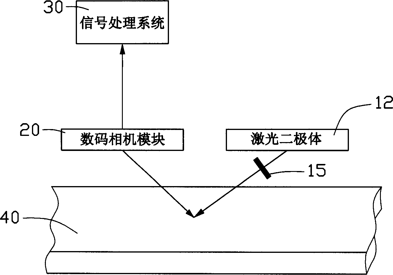
[0012] see figure 1 The real-time detection device of the present invention includes a laser diode 12 as a light source, a digital camera module 20, and a signal processing system 30, wherein a grating 15 is arranged on the optical path direction of the laser diode 12. The laser beam passing through the laser diode 12 is irradiated onto the substrate 40 , and the beam reflected by the substrate 40 is imaged by the digital camera 20 and sent to the signal processing system 30 for analysis and judgment.

[0013] The wavelength range of the laser diode 12 is 400nm-700nm, preferably 650nm, 405nm or any one shorter than the wavelength of blue light. In terms of light source, the output power is high, the modulation speed is fast, and the luminous angle is concentrated.

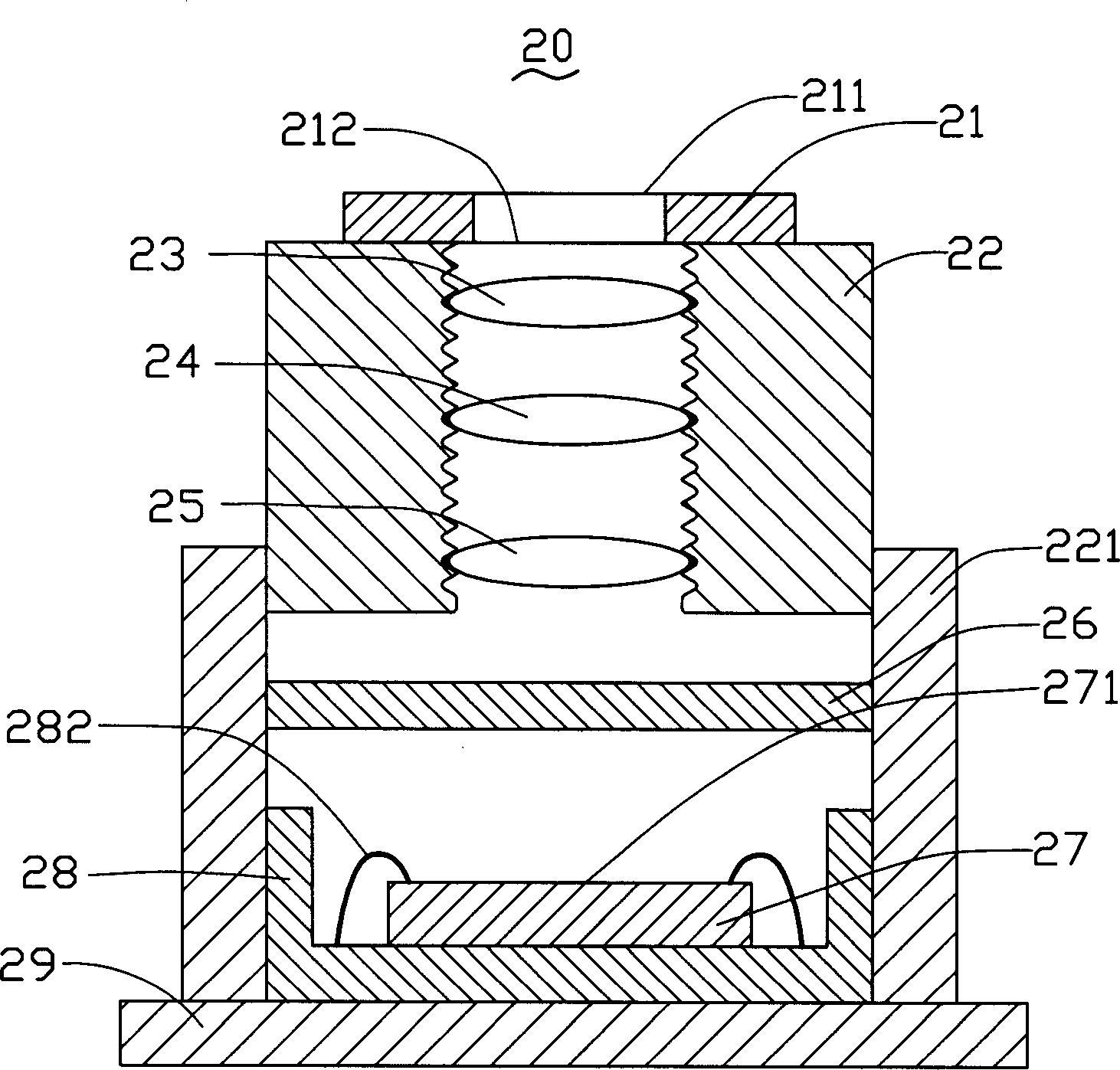
[0014] Please refer to the figure 2 The digital camera module 20 of the real-time detection device of the present invention includes a top cover 21, a lens barrel 22, a first lens 23, a second lens 24, a third l...


PUM

PropertyMeasurementUnit
wavelengthaaaaaaaaaa
sizeaaaaaaaaaa

Abstract

The real-time detecting device capable of being used in the real-time detection of substrate includes one signal processing system, one laser dipole and one digital camera assembly. The laser dipole is used in emitting laser beam to irradiate the substrate; the digital camera assembly is used in taking the image of the substrate surface; the signal processing system is used in analyzing the data from the digital camera assembly to judge whether to have fault in the substrate part, and the signal processing system, the laser dipole and the digital camera assembly are connected electrically. The real-time detecting device of the present invention has small size, and convenient and accurate detection.

Description

【Technical field】 [0001] The invention relates to a real-time detection device, in particular to a real-time detection device combined with a digital camera module. 【Background technique】 [0002] In precision machining, surface processing, electronic packaging and semiconductor manufacturing processes, real-time inspection of the processing process is usually required to ensure product yield. [0003] Taking the pre-processed substrate as an example, the current inspection equipment detects the substrate, and usually uses the Charge Coupled Device (CCD) camera in the equipment to cooperate with the floodlight group to inspect the substrate imported into the equipment. Image acquisition; then the image data is transmitted to the system host, which is analyzed and judged by the system host to detect the surface flatness of the substrate and whether there are scratches, etc., and provide a warning function for the production of the substrate, and mark it on the abnormal substr...

Claims


Application Information

Patent Timeline
Patent Type & Authority Applications(China)
IPC IPC(8): G01N21/21G01N21/88G06K9/00
CPCG01N21/21G01N21/8806
Inventor 陈杰良
Owner HONG FU JIN PRECISION IND (SHENZHEN) CO LTD
Why Eureka
Try Eureka