Insert for metal cutting
A technology of cutting inserts, inserts, applied in the field of intermediate and finishing, coarse and coated inserts of less chip-removing materials, which can solve problems such as limiting heat resistance and wear resistance
- Summary
- Abstract
- Description
- Claims
- Application Information
AI Technical Summary
Problems solved by technology
Method used
Image
Examples
example
[0024] Inserts tested in the following instances:
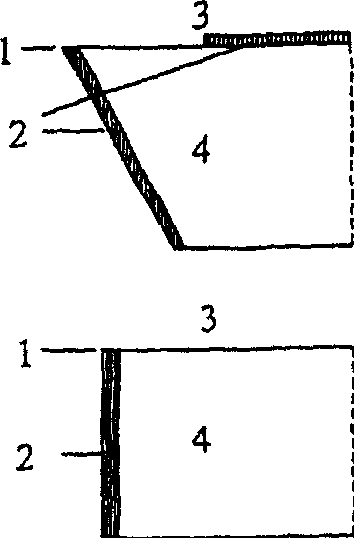
[0025] "A" inserts according to the present invention have a binder-rich surface region on the cutting edge and clearance faces, but no binder-phase-rich surface region on the rake face;
[0026] "B" inserts of the prior art, having a binder-phase-rich surface region on all surfaces bounding the cutting edge;
[0027] The "C" inserts, outside of the present invention, had no binder phase rich surface area on all surfaces.
[0028] The above test inserts A, B and C all had a cemented carbide body of similar chemical structure and similar physical overall properties.
example 1
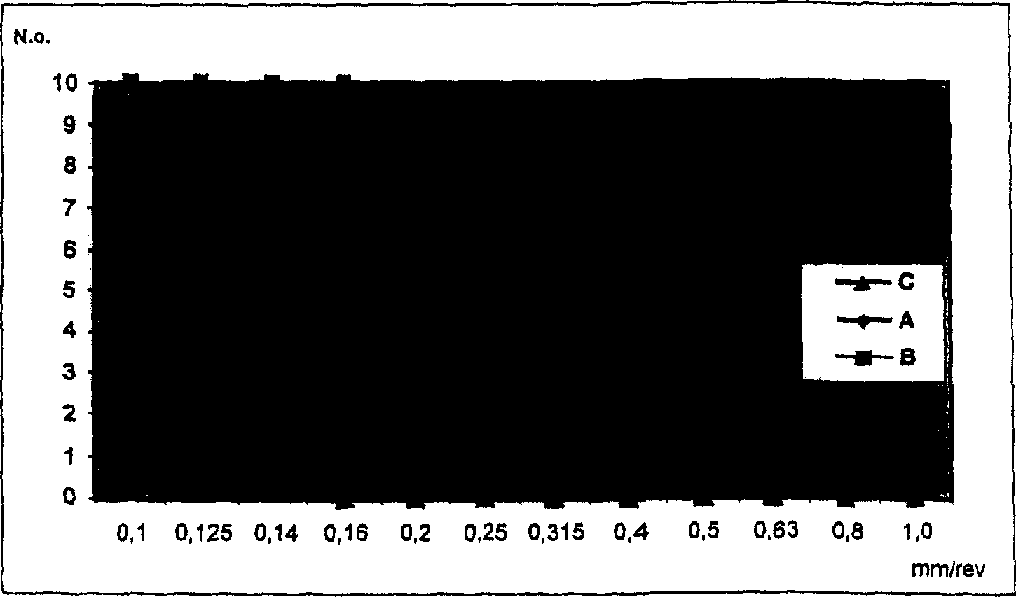
[0030] Blade "A" according to the invention was tested against blades "B" and "C". The total composition of the blade includes: 5.3 wt% Co, 3.3 wt% Ta, 2.1 wt% Nb, 2.0 wt% Ti, 6.0 wt% C, 0.2 wt% N and W as balance weight. The surface area of the insert base consists of a 25 μm thick binder-phase-rich fraction with little cubic carbonitride phase. After removal of the binder phase-rich surface region on the rake face surface, these substrates were coated with a 7 μm thick layer of TiC x N y o z layer, a layer of 5 μm thick AL composed of α-phase 2 o 3 layer as well as depositing 0.5 μm thick nitrogen-enriched TiC x N y o z outer layer.
[0031] These inserts were tested under the following conditions:
[0032] Workpiece: Cylindrical slotted rod
[0033] Material: SS1672-08, starting diameter 160mm
[0034] Blade type: CNMA120408
[0035] Cutting speed: 140m / min
[0036] Feed speed: increased from 0.1mm / rev to 1.0mm / rev
[0037] Cutting depth: 2.0mm
[0038] Cut...
example 2
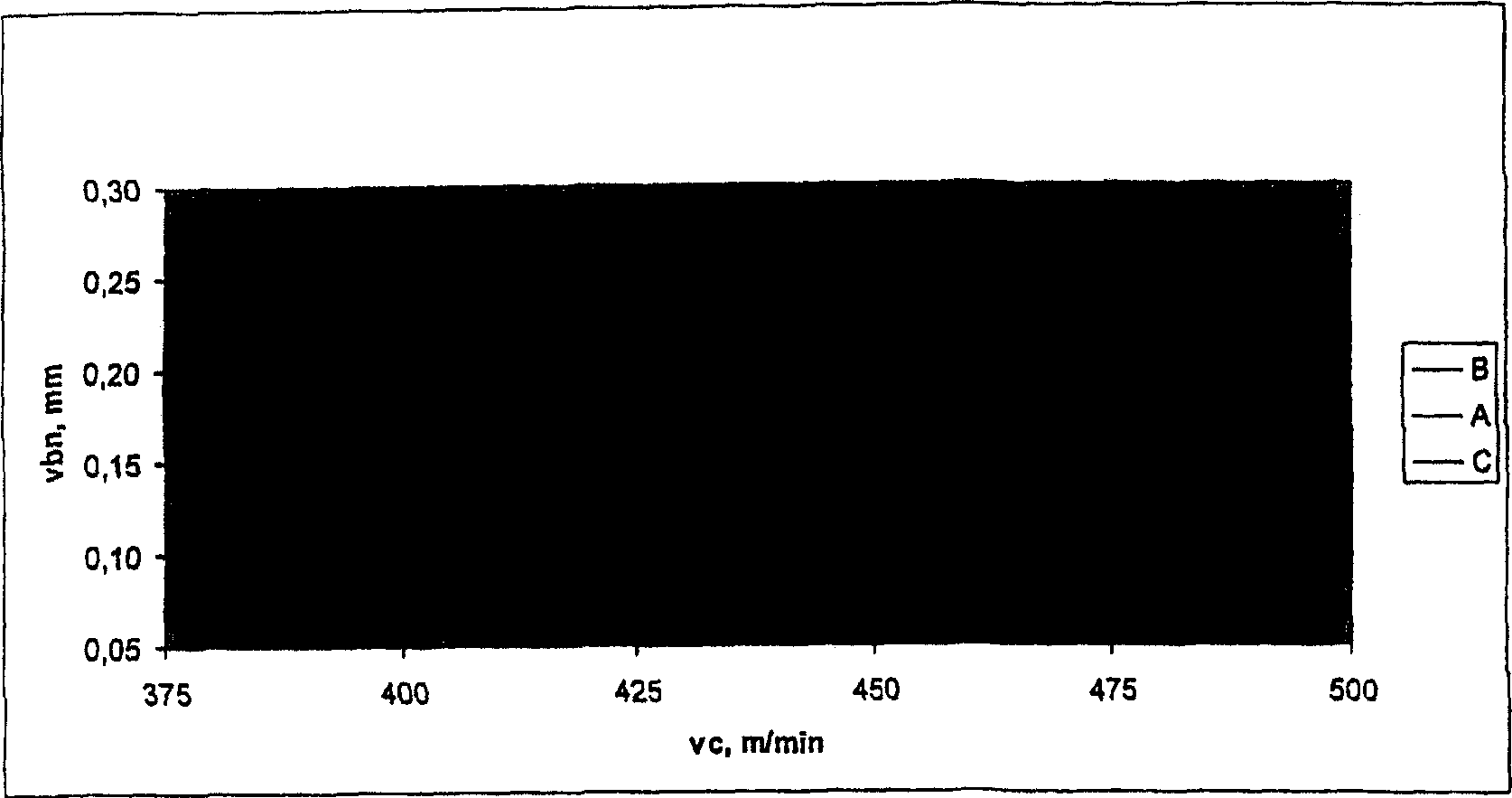
[0044] A, B and C inserts are compared in continuous metal cutting during ramp up. The blade base comprises: 7.6% by weight Co, 2.2% by weight Ta, 2.0% by weight Nb, 1.5% by weight Ti. The surface area of the insert base consists of a 30 μm thick binder-phase-rich fraction with little cubic carbonitride phase. After removing the gradient regions on selected surfaces, these substrates were coated with a 5 μm thick layer of TiC x N y o z layer, a layer of 8 μm thick α-Al 2 o 3 layer, and deposited 0.5 μm thick nitrogen-enriched TiC x Ny o z outer layer.
[0045] The test conditions are as follows:
[0046] Workpiece: cylindrical rod
[0047] Material: SS1672-08
[0048] Blade type: TPUN160308
[0049] Cutting speed: 300-550m / min
[0050] Feed speed: 0.3mm / rev
[0051] Cutting depth: 2.5mm
[0052] Cutting length: 10mm
[0053] Remarks: no coolant is used
[0054] Plastic deformation and / or flank wear (vbn) is detected at the point where the nose radius begins a...
PUM
| Property | Measurement | Unit |
|---|---|---|
| thickness | aaaaa | aaaaa |
| thickness | aaaaa | aaaaa |
| thickness | aaaaa | aaaaa |
Abstract
Description
Claims
Application Information
 - R&D
- Intellectual Property
- Life Sciences
- Materials
- Tech Scout
- Unparalleled Data Quality
- Higher Quality Content
- 60% Fewer Hallucinations
Browse by: Latest US Patents, China's latest patents, Technical Efficacy Thesaurus, Application Domain, Technology Topic, Popular Technical Reports.
© 2025 PatSnap. All rights reserved.Legal|Privacy policy|Modern Slavery Act Transparency Statement|Sitemap|About US| Contact US: help@patsnap.com


