Thermosensitive laser sculpturing machine and its sculpturing method
A laser engraving machine and heat-sensitive technology, applied in the direction of optomechanical equipment, microlithography exposure equipment, optics, etc., can solve the problems of limited output laser channel number, large volume, poor imaging quality, etc., and achieve fast processing speed and excellent imaging quality. Good quality and easy maintenance
- Summary
- Abstract
- Description
- Claims
- Application Information
AI Technical Summary
Problems solved by technology
Method used
Image

Examples
Embodiment 1
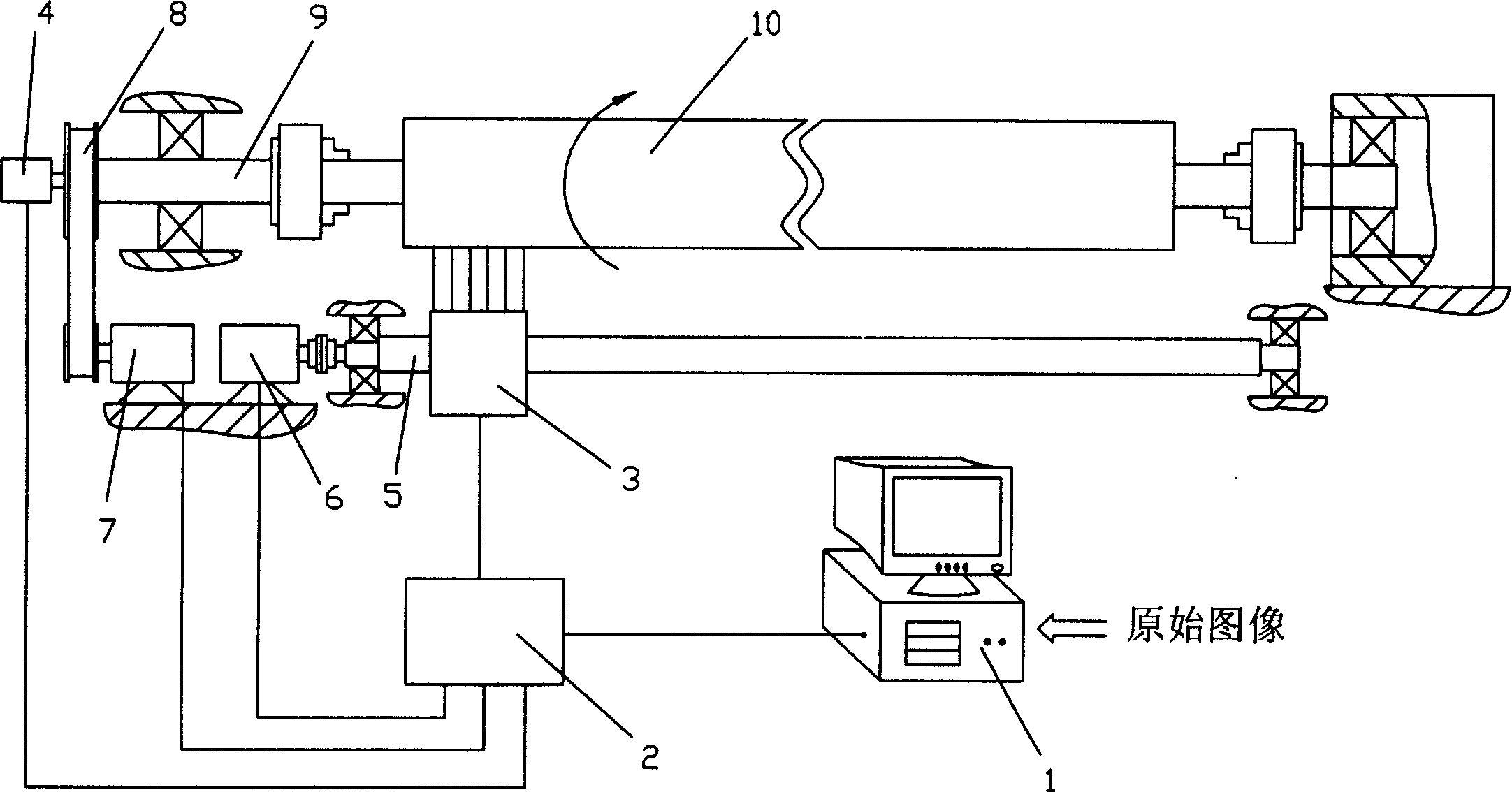
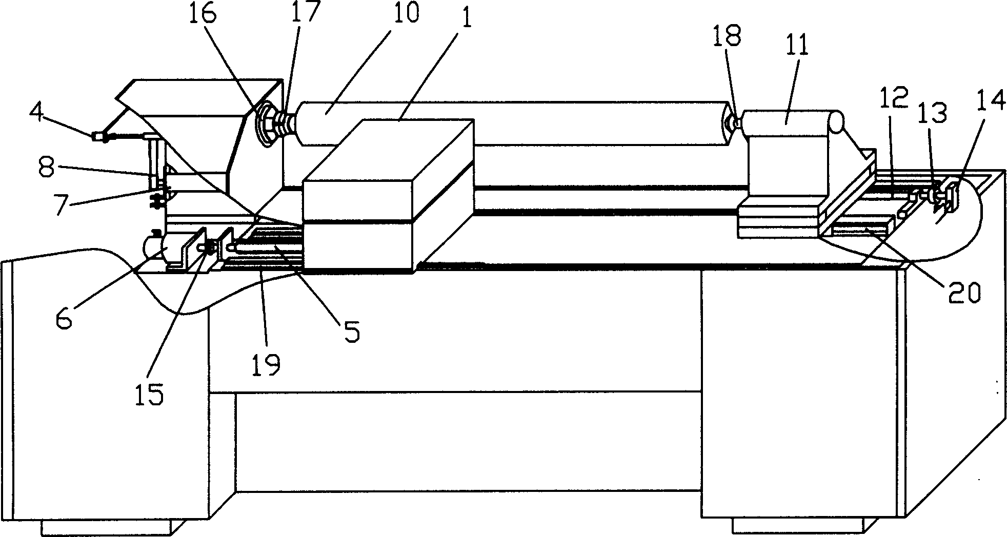
[0021] see image 3 The technical solution adopted by the present invention to solve the above technical problems includes an engraving method for a thermal laser engraving machine, which includes a computer 1, a controller 2, an optical engine 3, a grating encoder 4, a traverse mechanism, The transmission mechanism, the roller 10 and the tailstock mechanism, the transmission mechanism is connected with the roller 10 and the tailstock mechanism, the controller 2 is connected with the optical engine 3, the grating encoder 4, the traverse mechanism, the transmission mechanism, the tailstock mechanism and the computer 1 respectively Connected, the optical engine 3 is connected with the traverse mechanism, and the computer 1 is provided with a control program; the engraving method comprises the following steps:
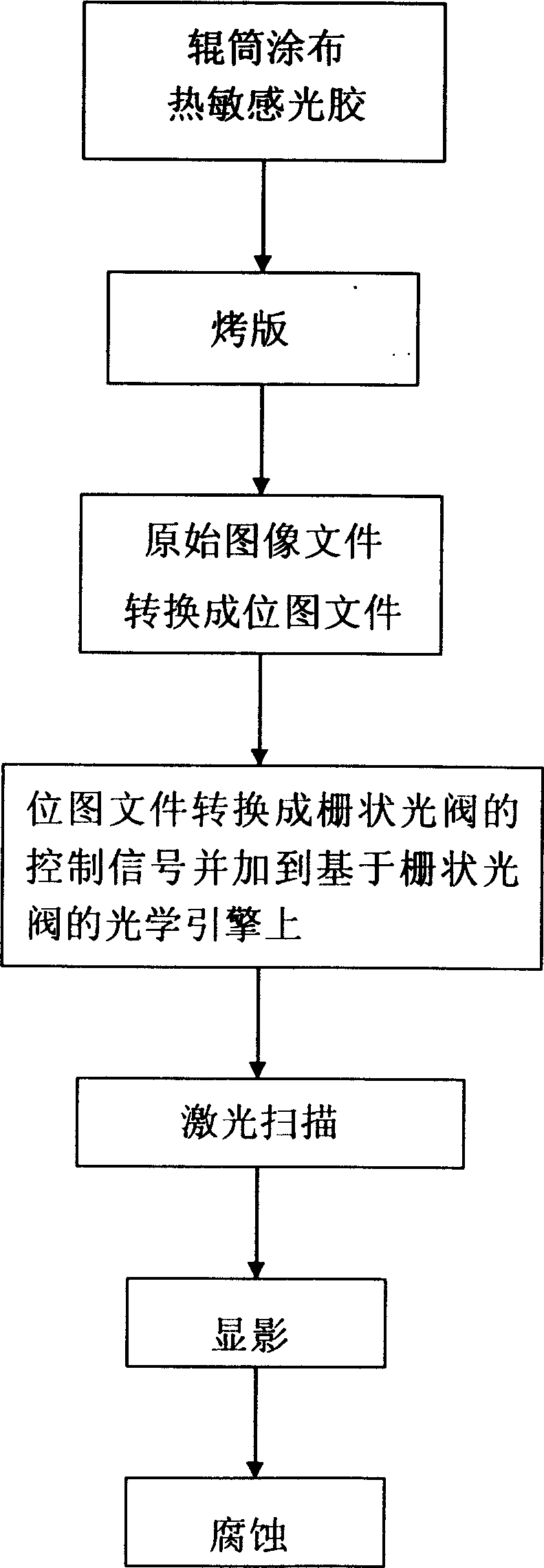
[0022] The roller 10 is coated with heat-sensitive photoresist,
[0023] baked plate,
[0024] Raw image files are converted to bitmap files,
[0025] The bitmap file ...
Embodiment 2
[0030] In this embodiment, the first three steps are:
[0031] Raw image files are converted to bitmap files,
[0032] Roller coated heat-sensitive photoresist,
[0033] baked version.
[0034] Following steps are with embodiment 1.
Embodiment 3
[0036] In this embodiment, the first three steps are:
[0037] Roller coated heat-sensitive photoresist,
[0038] Raw image files are converted to bitmap files,
[0039] baked version.
[0040] Following steps are with embodiment 1.
[0041] During specific implementation, at first the roller blank 10 through machining is coated with heat-sensitive photoresist and baked, turn on the power, start the computer 1, and the original image forms a bitmap file through the raster image processing in the control program of the computer 1 and sends it to the computer. To the controller 2, the controller 2 converts the bitmap file into a data string that matches the grid light valve drive circuit and sends it to the register of the grid light valve, thereby controlling the optical engine 3 to align the roller with the set image The cylinder blank 10 is processed by laser scanning. At the same time, the controller 2 controls the work of the grating encoder 4, the traverse motor 6, the ...
PUM
 Abstract
Description
Claims
Application Information
 - R&D
- Intellectual Property
- Life Sciences
- Materials
- Tech Scout
- Unparalleled Data Quality
- Higher Quality Content
- 60% Fewer Hallucinations
Browse by: Latest US Patents, China's latest patents, Technical Efficacy Thesaurus, Application Domain, Technology Topic, Popular Technical Reports.
© 2025 PatSnap. All rights reserved.Legal|Privacy policy|Modern Slavery Act Transparency Statement|Sitemap|About US| Contact US: help@patsnap.com