

Petroleum hydrocarbon catalytic conversion method
A catalytic conversion method and a technology for petroleum hydrocarbons, which are applied in the field of catalytic conversion of petroleum hydrocarbons, can solve problems such as ineffective contact problems, and achieve the effects of reducing the yield of dry gas, reducing the proportion of thermal cracking, and increasing the amount of circulation.
- Summary
- Abstract
- Description
- Claims
- Application Information
AI Technical Summary
Problems solved by technology
Method used
Image

Examples
Embodiment approach A
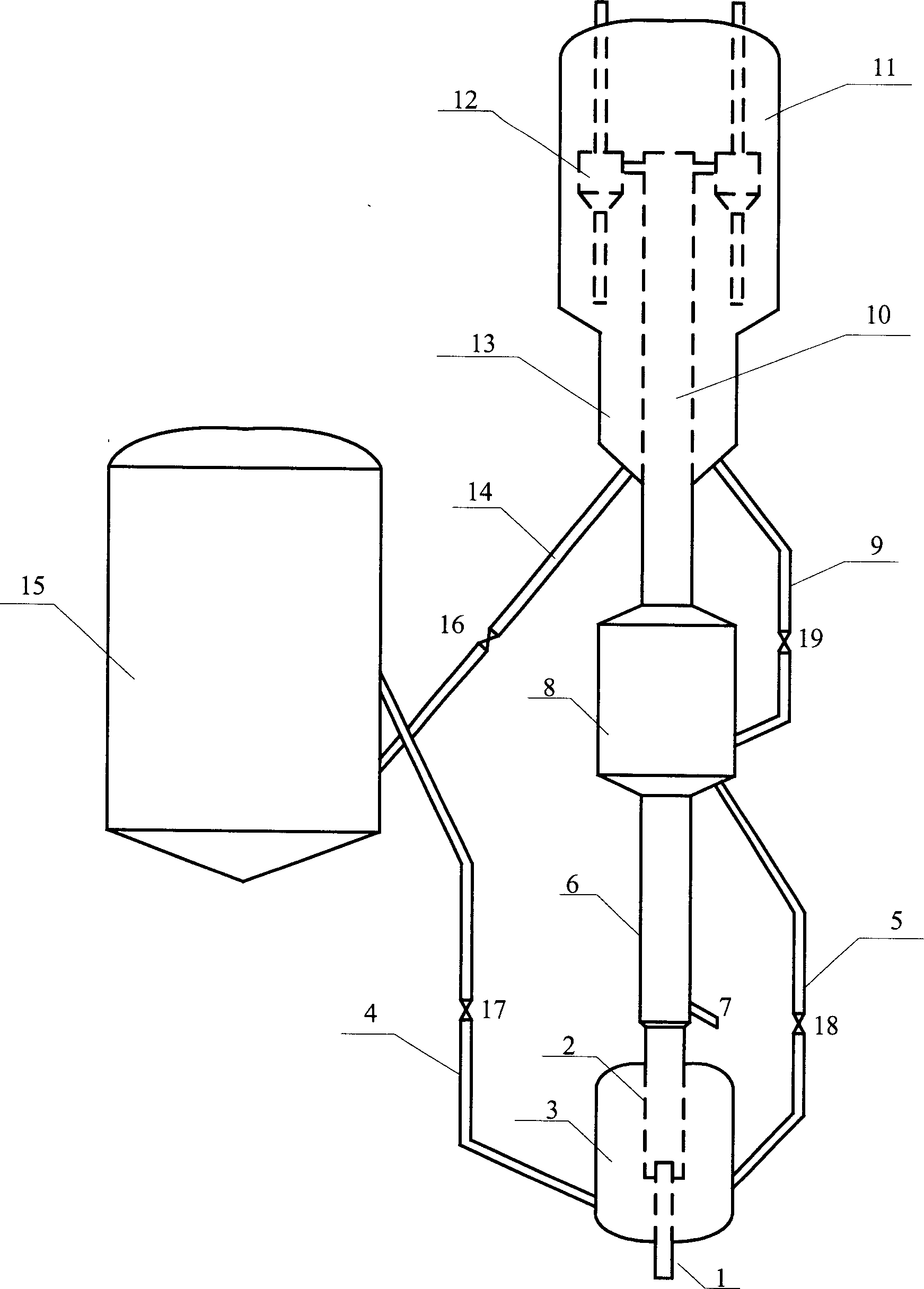
[0020] Implementation mode A: such as figure 1 As shown, for the variable-diameter riser reactor described in ZL99105903.4, a mixing zone is set at the bottom of the reactor. Its structural features are: along the vertical direction from bottom to top, there are mutually coaxial mixing zone, pre-lifting section, first reaction zone, second reaction zone with enlarged diameter, and outlet zone with reduced diameter. The size of the mixing zone is equivalent to the stripper in the catalytic cracking unit, which is coaxial with the riser and placed at the bottom of the riser. The high-temperature regenerant from the regenerator and the carbonized agent returned from the second reaction zone are mixed in the mixing zone, and the mixture is then contacted with raw oil to react, which can increase the ratio of agent to oil and reduce the dry gas yield; the above-mentioned mixture It goes up with oil and gas, reacts, and enters the second reaction zone. A part of the second reactio...
Embodiment approach B
[0021]Embodiment B: For a combined riser + fluidized bed reactor (the fluidized bed is located at the top of the riser), a mixing zone is set at the bottom of the reactor. Its structural features are: along the vertical direction from bottom to top, there are mutually coaxial mixing zone, riser (first reaction zone), fluidized bed (second reaction zone). The size of the mixing zone is equivalent to that of the stripper in the catalytic cracking unit, which is coaxial with the riser and placed at the bottom of the riser. The high-temperature regenerant from the regenerator and the carbonized agent returned from the second reaction zone are mixed in the mixing zone, and the mixture is then contacted with raw oil to react, which can increase the ratio of agent to oil and reduce the dry gas yield; the above-mentioned mixture And the reaction oil gas ascends, reacts, and enters the second reaction zone. A part of the second reaction zone carries the carbon agent back to the mixing...
Embodiment
[0027] This example illustrates: the product distribution and product properties obtained by the catalytic conversion reaction of hydrocarbon oil by using the method provided by the present invention.
[0028] The process flow of a medium-sized catalytic cracking unit is as follows: figure 1 As shown, the preheated raw oil is injected into the first reaction zone of the reactor through the pipeline 7, and contacts and reacts with the mixture in the reaction zone. The 700°C regenerant is mixed in the mixing zone at a ratio of 0.05:1, and the bed density in the mixing zone is 300kg / m 3 . The reaction temperature in the first reaction zone is 545°C, the reaction time is 1 second, and the ratio of solvent to oil is 5.5:1. The mixture of oil gas and catalyst goes up into the second reaction zone, and a part of the spent catalyst is returned from the stripping section to enter the second reaction zone. The ratio of the mass flow rate of the returned spent catalyst to the mass flow...
PUM
| Property | Measurement | Unit |
|---|---|---|
| density | aaaaa | aaaaa |
| density | aaaaa | aaaaa |
Abstract
Description
Claims
Application Information