
Non-routine reactor shutdown method

A reaction and reaction zone technology, applied in chemical instruments and methods, carboxylate preparation, carbon-based compound preparation, etc., can solve problems such as reactor fire or explosion, increased operational complexity, and reactor leakage reactions.

Inactive Publication Date: 2006-06-07
ROHM & HAAS CO
View PDF11 Cites 19 Cited by
  • Summary
  • Abstract
  • Description
  • Claims
  • Application Information

AI Technical Summary

Problems solved by technology

Given this possibility, one drawback of simply terminating the feed to the reactor is that potentially explosive mixtures may become trapped in the reactor
In addition, when the feed and feed are stopped or excessively reduced, there is no way to vent the reactor, and the possibility of reactant and product reflux (i.e., backflow) into the reactor increases.
Therefore, the procedure of simply terminating and reducing the feed of material to the reactor does not eliminate the hazardous condition and still leaves the reactor with the potential for fire or explosion
[0010] Termination of flow into the reactor also does not respond appropriately to other adverse conditions, such as loss of reactor volume (e.g., reactor leak) or runaway reaction during the reaction
This means that the same response cannot be used for multiple parking scenarios, thus increasing operational complexity

Method used


Image

  • Non-routine reactor shutdown method
  • Non-routine reactor shutdown method

Examples


Embodiment 1

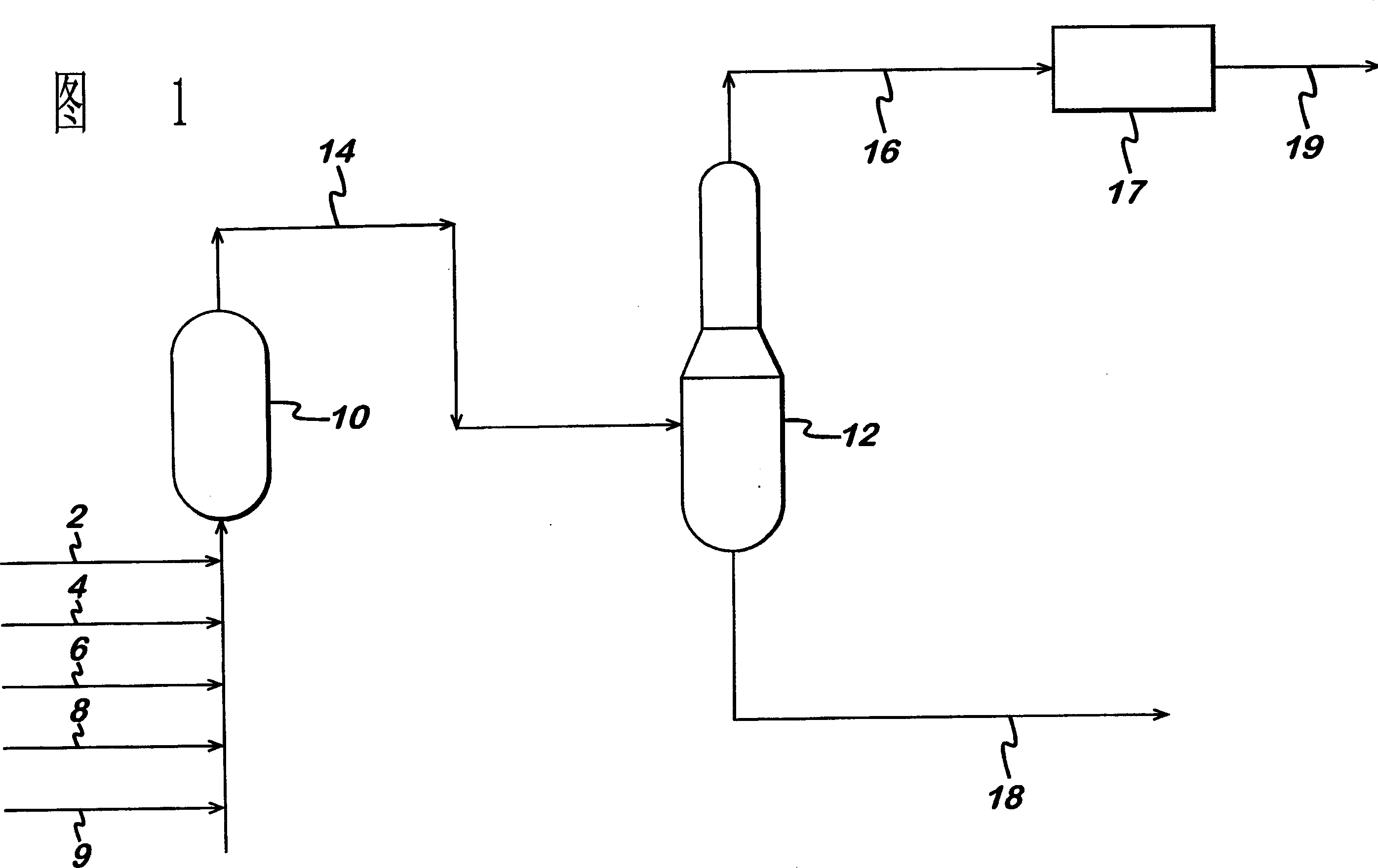
[0059] In a non-limiting embodiment of the method of the present invention, a series of unfavorable reaction process conditions for the partial catalytic oxidation process for the production of acrylic acid are enumerated. During the reaction of this example, a plurality of contacting shell-and-tube reactors were continuously supplied with a total feed of propylene, air and inert material (steam), and one or more commercially available molybdenum-oxidized In the presence of a material MMO catalyst, under sufficient process conditions to oxidize propylene to acrolein and acrylic acid. Listed identified adverse reaction process conditions include, but are not limited to:

[0060] · Flammable reactor feed mixture

[0061] · High reactor pressure

[0062] ·Reaction process leakage

[0063] Runaway reaction / rapid catalyst temperature rise

[0064] · High catalyst temperature

[0065] ·Low catalyst temperature

[0066] Incorrect reactant to oxidant feed ratio

[0067] Incorre...

Embodiment 2

[0081] In one non-limiting embodiment of the invention, the reaction process occurs as part of the chemical process for producing acrylic acid. The chemical process consists of two shell-and-tube reactors connected in series with an auxiliary intercooler (herein referred to as "tandem reactors") with an absorber downstream of the series reactor and receiving heat from the absorber overhead stream. oxidizer. Each shell-and-tube reactor vessel consisted of about 10,000 tubes with a diameter of 1.5" (37.5 mm) packed with a commercially available molybdenum-oxide (MMO) oxide catalyst. The reactors in series and their auxiliary tubes The volume is approximately 5557 cubic feet (157 cubic meters).The process of this example also includes a computer-based control system capable of sensing adverse conditions in the chemical process.

[0082] Under normal operating circumstances, a total feed of propylene, air and steam is continuously provided to the reaction process under process co...


PUM


Abstract

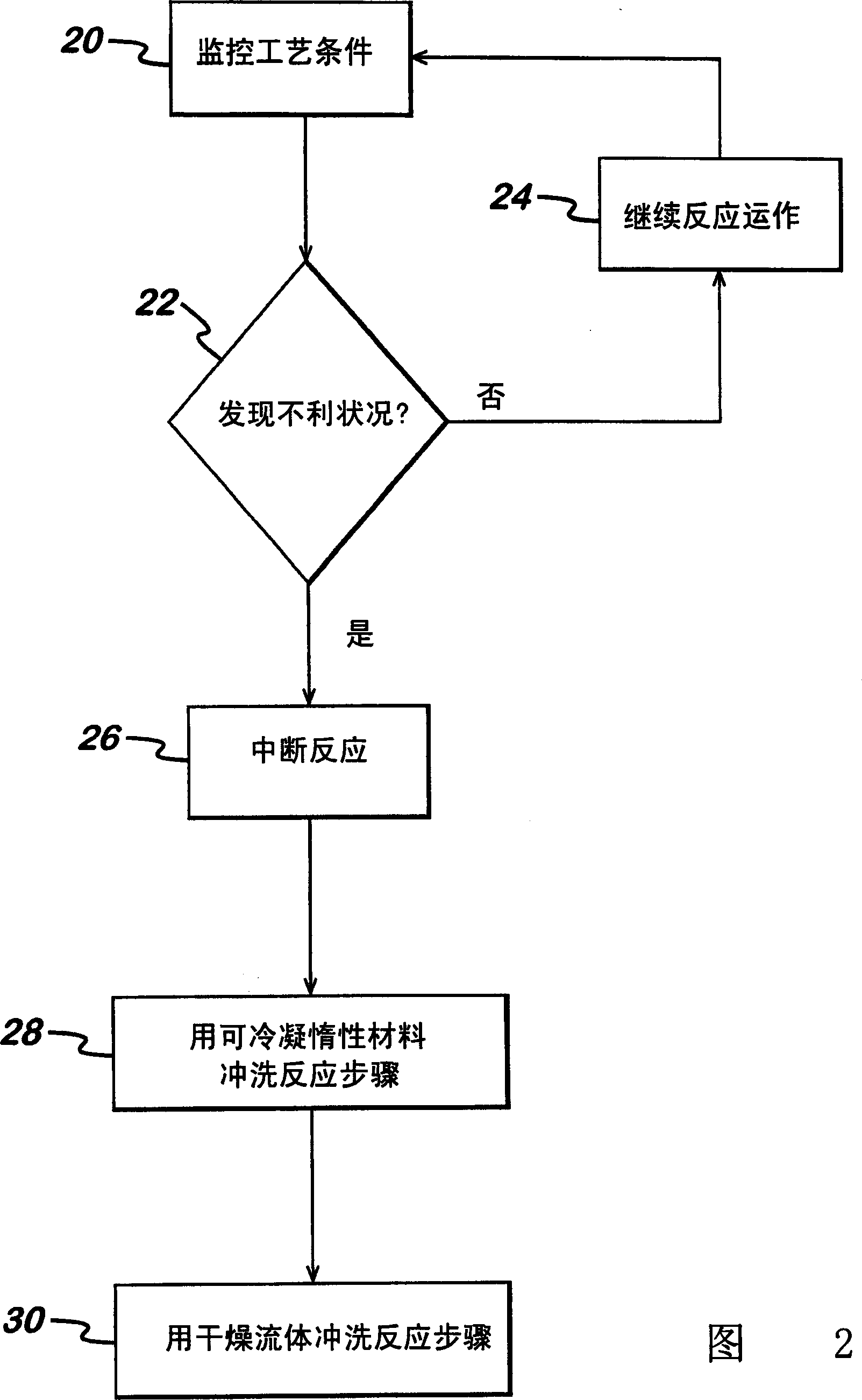
Abnormal (i.e., emergency) shutdown of a chemical reaction process is accomplished by a method of safely operating a chemical reaction process that includes the steps of detecting adverse conditions that can affect the reaction process, minimizing the reaction of reactants, and maintaining The flow of material in the reaction zone of the process to displace the reaction mixture from the reaction zone. The flow of material is maintained for a period of time to displace substantially all of the reaction mixture from the reaction zone, thereby flushing the reaction zone. The reaction mixture can then be flushed into an auxiliary vessel, such as an absorption column.

Description

technical field [0001] The present invention relates to a method of operating chemical process hardware during an emergency shutdown situation, and more particularly, the present invention relates to a method of monitoring a partial oxidation reaction process and safely stopping the reaction process when required. Background technique [0002] The chemistry for preparing oxidation products such as carboxylic acids, anhydrides, nitriles and alkylene oxides is well known. The core of these chemical processes is the partial oxidation reaction method, which includes a catalytic oxidation reactor with controllable conditions such as temperature, pressure and reaction rate. These reaction processes generally involve providing a feedstock, such as a mixture of reactive hydrocarbons and oxygen, to one or more reaction zones contained within a reaction apparatus. Each reaction zone contains one or more catalysts capable of catalyzing the oxidation of active hydrocarbons to various o...

Claims


Application Information

Patent Timeline
IPC IPC(8): B01J19/00B01J8/02C07C51/25C07C57/00
CPCB01J19/002B01J2208/00637B01J2219/00164B01J2219/002B01J2219/00225B01J2219/00231B01J2219/00261B01J2219/00263B01J2219/00272C07C45/33C07C45/35C07C46/06C07C51/215C07C51/252C07C51/265C07C51/313C07C47/22C07C50/18C07C57/04C07C63/16B01J8/00B01J19/00
Inventor M·S·德库西N·Q·李
Owner ROHM & HAAS CO
Learn More