New bonding and assembling process for slow wave circuit of microwave tube and its bonding agent cleaning system

A slow-wave circuit and cleaning system technology, which is applied to the circuit components, electrical components, and manufacturing tools of transit-time electronic tubes, can solve problems such as the inability to completely remove adhesives, save cleaning solvents, and improve high-frequency Features, simple structure effect

Inactive Publication Date: 2006-07-19
NANJING UNIV OF TECH
View PDF0 Cites 8 Cited by
  • Summary
  • Abstract
  • Description
  • Claims
  • Application Information

AI Technical Summary

Problems solved by technology

In addition, this assembly method requires that the adhesive must be completely removed at the end to ensure the normal operation of the microwave tube, and the method of removing the adhesive is the burning method in addition to the cleaning method. Since the microwave tube device cannot be burned in an oxygen atmosphere, it can only be changed. Using the hydrogen burning method, the experiment proves that the hydrogen burning method cannot completely remove the adhesive, so the solvent cleaning method is ideal, and the present invention has developed a binder cleaning system

Method used


Image

  • New bonding and assembling process for slow wave circuit of microwave tube and its bonding agent cleaning system
  • New bonding and assembling process for slow wave circuit of microwave tube and its bonding agent cleaning system
  • New bonding and assembling process for slow wave circuit of microwave tube and its bonding agent cleaning system

Examples


Embodiment 1

[0034] The new process of bonding and assembling microwave tube slow wave circuit of the present invention has the following steps:

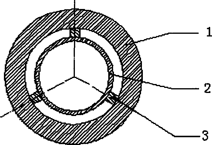
[0035] a) First, accurately position the three clamping rods on the helix with the core rod at an angle of 120 degrees, and then apply adhesive to bond the clamping rod and the helix. Molding agent, the beam is a rectangular inner groove structure with a taper angle, the upper inner groove is an inverted T-shaped groove, the clamping rod is embedded below the taper angle, and then the positioning agent is applied in the groove of the beam, and then the The axis of the core rod is accurately positioned on the axis of the main positioning block. There are two main positioning blocks, which are regular hexagonal structural parts. Six positioning holes are uniformly arranged around each main positioning block. Two main positioning blocks It is fixed by 6 steel rods closely matched with the positioning holes, and the distance between them depends on ...

Embodiment 2

[0049] Method and technology are with embodiment 1, and difference is as follows Figure 8 The cleaning jig 24 shown is placed vertically. When placed vertically, the flow direction of the cleaning liquid is vertically downward, and the washing direction of the liquid is consistent with the direction of gravity, so the washing effect is better. The direction of gravity is consistent. During the flushing process, the inner core may be flushed away from the assembly position, causing flushing to be scrapped; while flushing in the horizontal position, the liquid flushing direction is perpendicular to the direction of gravity, and the flushing effect is worse than that in the vertical position. The scouring force on the inner core component of the microwave tube is perpendicular to the direction of gravity, and it is relatively difficult to wash away from the assembly position. These two methods can be easily switched as needed.


PUM


Abstract

The invention relates to a microwave slow-wave circuit adhere installment technique, which also discloses relative cleaning system of said adhesive. The inventive microwave slow-wave circuit can improve the high-frequency property of microwave tube. The inventive cleaning system can clear the adhesive and save the consumed solvent, with simple structure, continuous operation, and high safety. The inventive technique comprises: first sticking three ceramic clamping rods with adhesive on the integration of screw line and core rod in 120 degree; then abrading the outer round of integration; pushing the integration and the microwave tube in interference fit with special device into the tube case; and removing the adhesive.

Description

technical field [0001] The present invention relates to a microwave tube circuit assembly process, more specifically to a new process for bonding and assembling a microwave tube slow wave circuit. Mixture cleaning system. Background technique [0002] At present, most domestic microwave tube slow-wave circuit assembly adopts mechanical methods such as elastic deformation clamping assembly method or expansion clamping assembly method, but this method will greatly limit the high-frequency characteristics of microwave tubes, thereby also limiting the power of small and medium power microwaves in my country. Tube manufacturing level. [0003] In order to improve the high-frequency characteristics of microwave tubes, thereby improving the manufacturing level of my country's small and medium-power microwave tubes, it is imperative to develop a new process for assembling microwave tube slow-wave circuits. A new process of slow wave circuit bonding assembly, and developed its relate...

Claims


Application Information

Patent Timeline
Patent Type & Authority Applications(China)
IPC IPC(8): H05K13/04H01J23/24B08B3/00B08B13/00B25B11/00
Inventor 鲁钢魏无际
Owner NANJING UNIV OF TECH
Why Eureka
Try Eureka