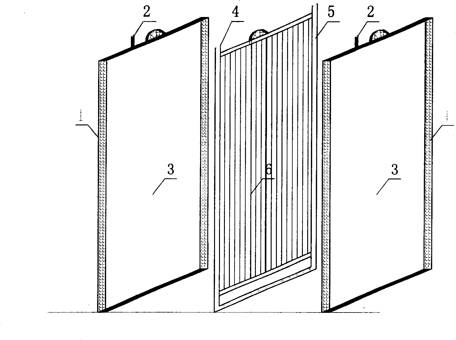
Combined membrance assembly

A membrane module and combined technology, which is used in the research and development and application of membrane separation technology, can solve the problems of accelerated pollution, dead angle, and increased energy consumption of membrane modules.

Inactive Publication Date: 2006-08-09
RES CENT FOR ECO ENVIRONMENTAL SCI THE CHINESE ACAD OF SCI
View PDF0 Cites 7 Cited by
  • Summary
  • Abstract
  • Description
  • Claims
  • Application Information

AI Technical Summary

Problems solved by technology

[0002] Membrane technology has attracted widespread attention in the water treatment industry because of its reliable effluent quality and simple and convenient operation methods. However, problems such as expensive membranes and flux attenuation caused by membrane fouling have seriously hindered the promotion and application of membrane technology.
Modules using flat membranes generally have the advantages of simple manufacturing and assembly, convenient operation, easy membrane maintenance, chemical cleaning and replacement, but there are also disadvantages such as more complicated sealing, serious pressure loss, and lower packing density than tubular membranes. Applications usually require larger membrane modules (Gu Guowei, He Yiliang. Membrane bioreactors - research and application in sewage treatment. Beijing, Chemical Industry Press, 2002; N.Cicek.A review of membrane bioreactors and their potential application in the treatment of agricultural waste water. Canadian Biosystems Engineering, 2003, Vlo.45, 6.37-6.49)
At the same time, in terms of membrane pollution control, due to the installation characteristics of the flat membrane, the gap between the unit membranes is small, and it is easy to form a dead angle on the membrane surface. In order to prevent the deposition of sludge on the membrane surface and reduce pollution, it is necessary to increase the flow rate and The way to improve the flow channel to solve the problem of controlling membrane fouling has resulted in increased energy consumption and complex components (Jin Kie Shim, Ik-Keun Yoob, Young Moo Lee. Design and operation considerations fbr wastewater treatment using a flat submerged membrane bioreactor. Process Biochemistry 38 (2002) 279-285; M. Gander, B. Jefferson, S. Judd. Aerobic MBRs for domestic wastewater treatment: a review with cost considerations. Separation and Puurification Technology 18 (2000) 119-130)
At present, when flat membranes are used in sewage treatment systems, the methods provided by major membrane manufacturers to control membrane fouling are basically aeration and scouring. Uneven flushing of the membrane surface leads to accelerated fouling of the membrane components

Method used


Image

  • Combined membrance assembly

Examples


Embodiment Construction

[0006] Will contain COD 200~500mg / L, BOD 5 100~300mg / L, ammonia nitrogen 50~160mg / L, SS 20~50mg / L domestic sewage enters the activated sludge membrane bioreactor for treatment. 0.4m 3 / hr, temperature 12~29℃, pH 6.5~8.0, stable operation for 6 months. The flat membrane flux in the new membrane module is stable at 40L / m 2 h, the flux of the hollow fiber membrane module is stable at 14L / m 2 h, the operating pressure is 18-22kpa, and the treatment effect is stable. The COD value of the system effluent varies between 10 and 30mg / L, and is generally stable below 20mg / L. 5 The value fluctuates between 1 and 3mg / L, the ammonia nitrogen is stable below 10mg / L, the SS is stable below 0.3mg / L, and the effluent water quality meets the "Urban Sewage Recycling-Urban Miscellaneous Water Quality" (GB / T18920-2002) standard .


PUM


Abstract

The invention supplies new type combined type film component that is alternate installing board frame film component and hollow fiber film component. The hollow fiber film component is made up of film thread, pumping collector pipe, and washing aerator pipe. The feature is that the invention combines the advantage of flat film component and hollow fiber film component to make the installation easy and filling density and area effectively increase. The invention realizes the control of film pollution, and the function for mechanically washing the film, and improves the running flux of flat film component, etc.

Description

technical field [0001] The invention belongs to the technical field of research and development and application of membrane separation technology, and in particular relates to a novel membrane module combining a flat membrane and a hollow fiber membrane. Background technique [0002] Membrane technology has attracted widespread attention in the water treatment industry because of its reliable effluent quality and simple and convenient operation methods. However, problems such as high membrane prices and flux attenuation caused by membrane fouling have seriously hindered the promotion and application of membrane technology. [0003] Membrane module designs come in many forms, and they are all designed according to two membrane configurations: flat-sheet membrane and tubular membrane. Plate and frame and roll membrane modules use flat membranes, and tubular, capillary and hollow fiber membrane modules all use tubular membranes. Plate-and-frame membrane module is the earliest ...

Claims


Application Information

Patent Timeline
IPC IPC(8): C02F1/00C02F3/10
CPCY02W10/10
Inventor 樊耀波李刚董春松黄霞吴志超
Owner RES CENT FOR ECO ENVIRONMENTAL SCI THE CHINESE ACAD OF SCI
Why Eureka
Try Eureka