Mechanical hole punch

A technology of mechanical transmission and punching machine, applied in metal processing, etc., can solve problems such as complex system structure, high production cost, troublesome installation, commissioning and maintenance, etc., and achieve high punching precision, low equipment noise, simple and reasonable structure Effect

Inactive Publication Date: 2006-11-08
应书波
View PDF1 Cites 4 Cited by
  • Summary
  • Abstract
  • Description
  • Claims
  • Application Information

AI Technical Summary

Problems solved by technology

[0004] The above-mentioned Chinese Patent Application No. 02136287.4 adopts the image capture system (CCD) and images on the display of the invention patent of the "Numerical Control Punching Machine for Automatic Image Alignment" of the "Numerical Control Punching Machine" of 02136287.4. The workpiece is automatically corrected to the correct position; the punching power device, the viewing cylinder of the image capture system, the astigmatism sheet feeding device, and the die feeding mechanism all use pneumatic devices; the system structure is relatively complicated, and installation, debugging and maintenance More troublesome, relatively high production costs

Method used


Image

  • Mechanical hole punch
  • Mechanical hole punch
  • Mechanical hole punch

Examples


Embodiment Construction

[0023] The present invention will be further described in detail below in conjunction with the accompanying drawings and embodiments.

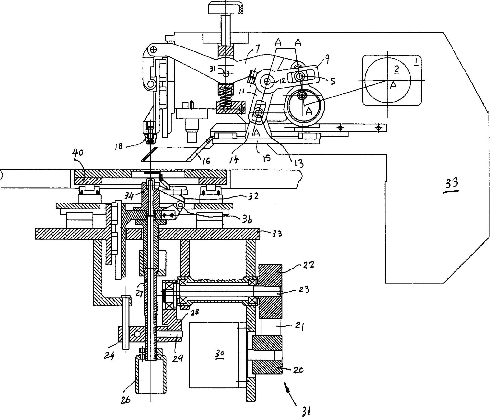
[0024] Figure 1 to Figure 3 An embodiment of the mechanically driven punching machine of the present invention is shown. It comprises a body 33 with an inner cavity, and a punching power device is installed in the inner cavity of the body 33, and the punching power device is connected with a punch 18 with an upper die and a viewfinder; a moving panel 40 is arranged below the body 33, and the moving panel 40, the upper fixing device has a workpiece clamping device; the lower device of the moving panel 40 has a lower mold transmission device and a scattering mechanism.

[0025] The work of the punch 18 of the band upper mold of the mechanical transmission punching machine of the present invention and the viewfinder mechanism is implemented in this way: see

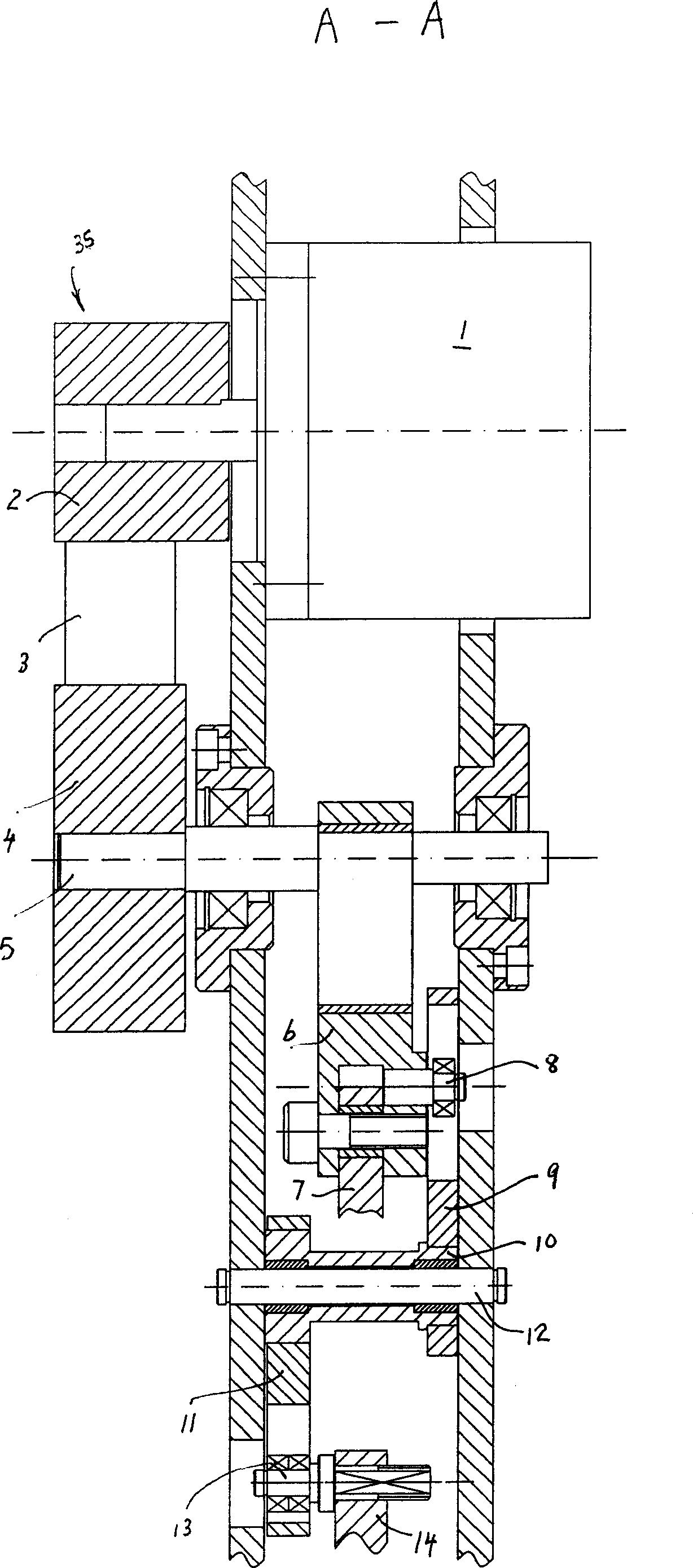
[0026] figure 2 As shown, the motor 1 is connected to a synchronous pulley 2, and t...


PUM


Abstract

The mechanical punch includes one frame, one power device connected to a ram head with upper mold, one viewing device connected to the power device, one movable panel with workpiece holder, one lower mold driving device and one scattering mechanism. The power device includes a motor, a sync belt wheel transmitting pair, a crank, a link rod, an upper mold swing link and an upper mold. The viewing device includes a swing rod, a driven swing rod, a viewing bar with viewing frame. The lower mold driving device and the scattering mechanism include a motor and a lower mold driving pair. The present invention has the advantages of simple and reasonable structure, high use reliability, high punching efficiency, low noise and easy maintenance.

Description

technical field [0001] The invention relates to a punching machine, in particular to a mechanically driven punching machine, which is suitable for punching standard process holes of printed circuit boards and signage industries. Background technique [0002] The applicant has authorized the Chinese Patent Application No. 02136287.4 for the invention patent of "Numerical Control Punching Machine with Automatic Image Alignment", which includes a body, a punching cylinder, a punching lever and its power device, and a punch guide slider , punch movement system, lever type floating fulcrum adjustment mechanism, image capture system (CCD), oblique astigmatism system; On the display, the computer automatically recognizes the bullseye error, and converts the error signal into a feed signal and sends it to the stepping motor to automatically correct the workpiece to the correct position, and start and complete the punching process. The punching power device, the viewfinder cylinder ...

Claims


Application Information

Patent Timeline
Patent Type & Authority Applications(China)
IPC IPC(8): B26F1/02B26D5/14B26D7/02B26D7/26
Inventor 应挺
Owner 应书波
Why Eureka
Try Eureka