

Sealed rechargeable battery and manufacturing method of the same
A secondary battery, airtight technology, used in secondary battery manufacturing, secondary batteries, battery pack components, etc., can solve problems such as reduced caulking force, inability to interrupt current paths, and increased contact resistance of internal components
- Summary
- Abstract
- Description
- Claims
- Application Information
AI Technical Summary
Problems solved by technology
Method used
Image

Examples
Embodiment approach
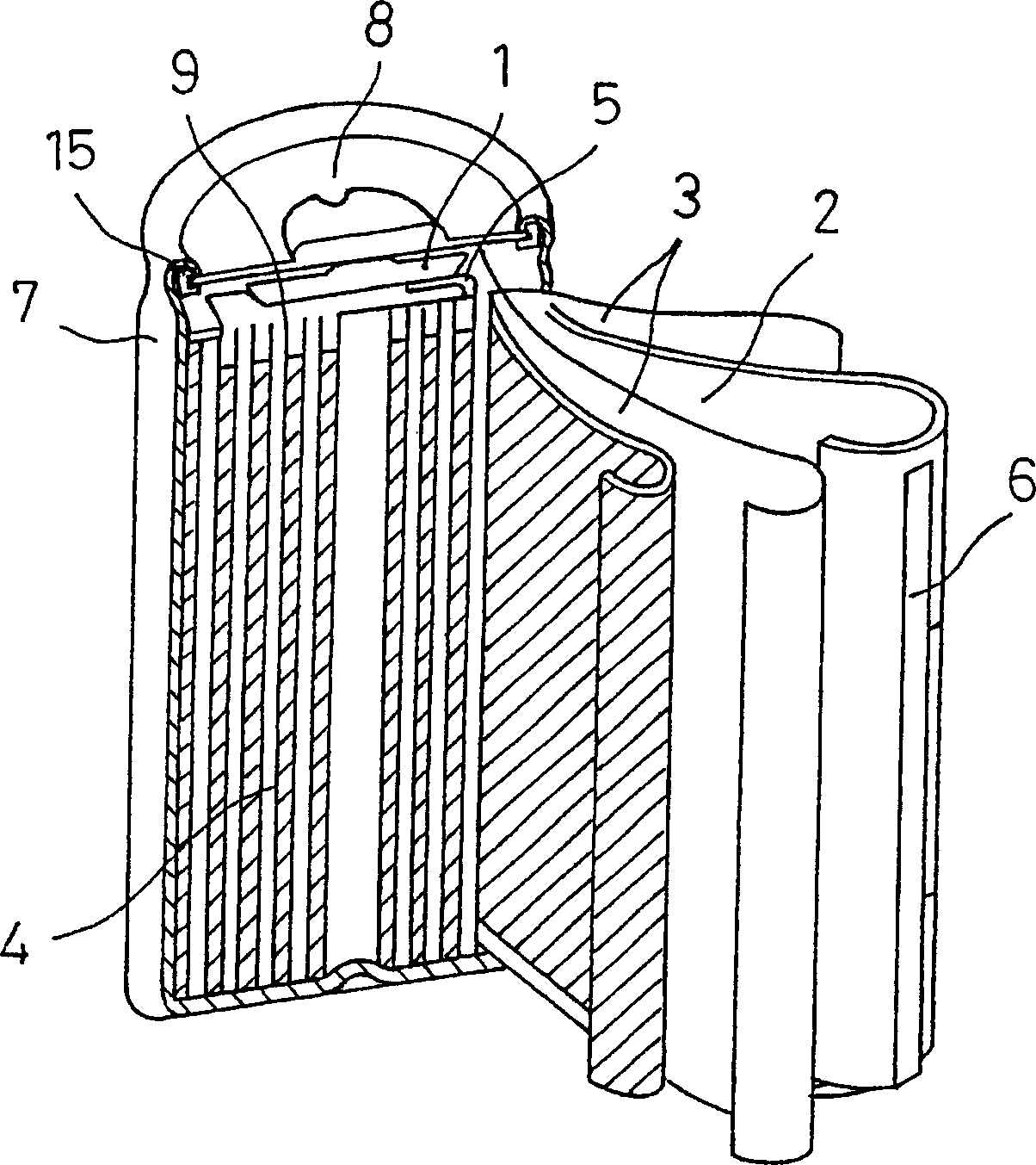
[0024] Next, with regard to the sealed secondary battery according to the embodiment of the present invention, while referring to the attachment of the cylindrical lithium ion battery with the most remarkable effect, Figure 1 side to explain.
[0025] figure 1 is a schematic longitudinal sectional view of a cylindrical lithium ion battery according to an embodiment of the present invention. exist figure 1 Among them, the cylindrical lithium-ion battery has a cylindrical plate group 4 wound into a spiral shape, wherein the plate group 4 is configured with: a positive electrode plate 1 coated with a positive electrode mixture on an aluminum foil current collector; A negative electrode plate 2 coated with a negative electrode mixture on a foil current collector; and a diaphragm 3 with a thickness of 25 μm between the two electrodes. The positive electrode lead current collector 5 was welded to the aluminum foil current collector by laser welding. The negative electrode lead ...
Embodiment 1
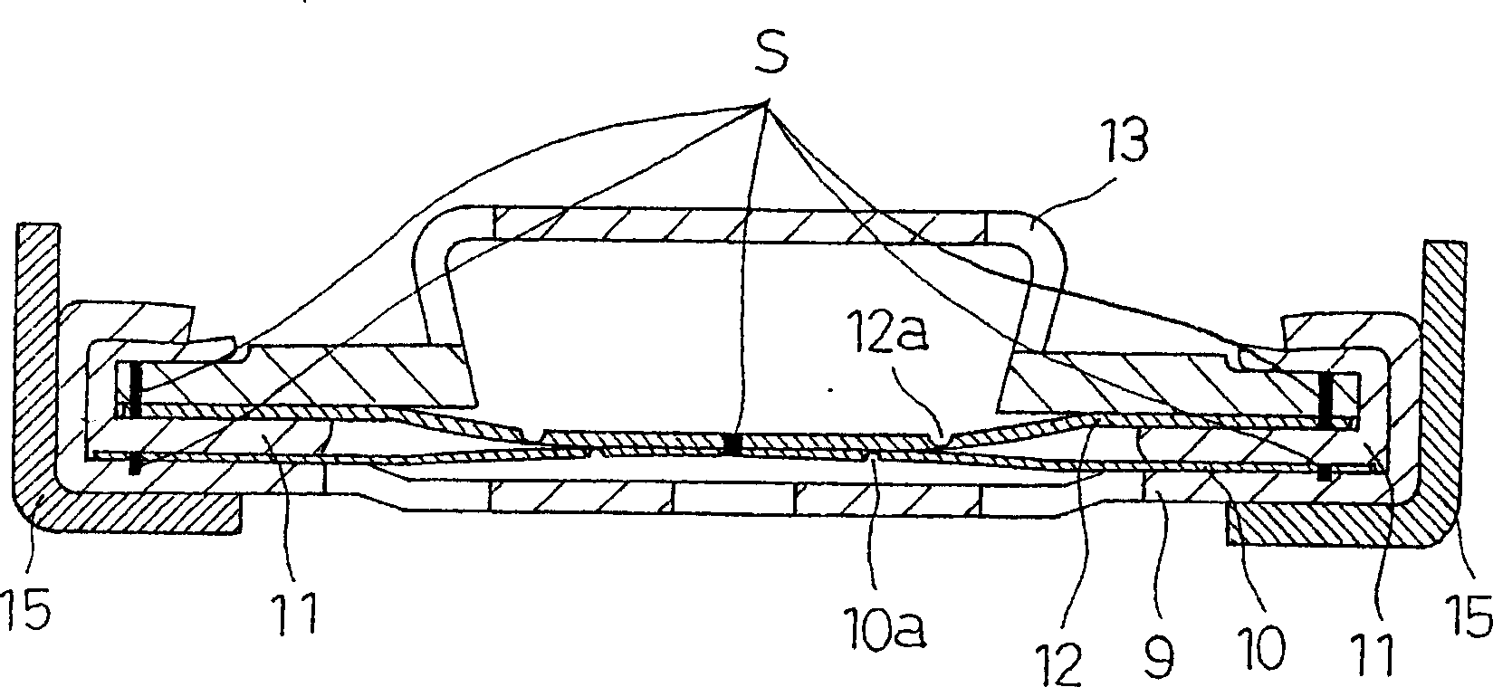
[0036] figure 2 It is a configuration diagram of the sealing plate of the sealed secondary battery of the present invention. exist figure 2 Among them, the sealing plate 8 is manufactured as follows. First, aluminum is press-worked to produce a disk-shaped metal filter 9 having a plurality of openings. Next, aluminum with a thickness of 0.15 mm was punched into a disc shape, and a circular thin-walled portion 10 a was formed in the center by marking, thereby producing the metal thin-walled valve body 10 . Next, polybutylene terephthalate (PBT) resin is injection-molded to produce a resin-made inner liner 11 of a predetermined size. Next, after punching out aluminum with a thickness of 0.15 mm into a disk shape, a C-shaped thin wall portion 12 a was formed at the center to manufacture a metal explosion-proof valve body 12 . The metal cap 13 is produced by press-working iron and then plating it with a nickel plating layer of about 3 μm. The components of the sealing plate...
Embodiment 2
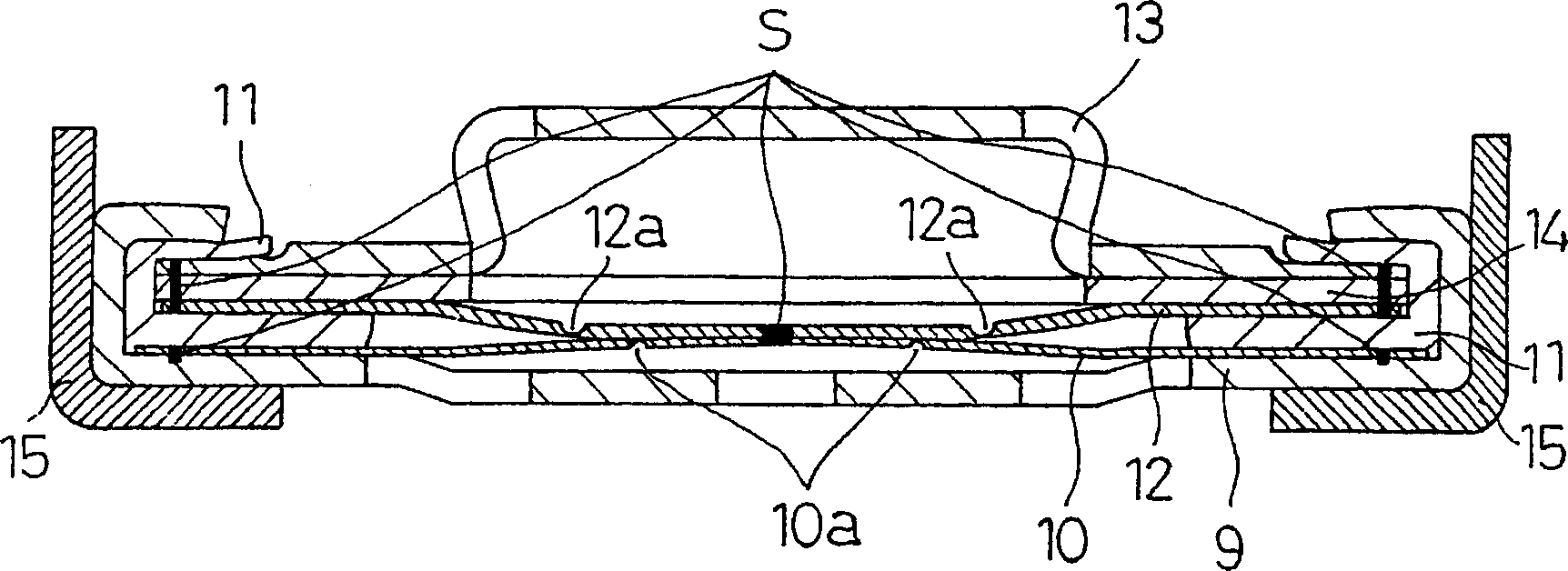
[0042] image 3 It is a configuration diagram of another sealing plate 8 of the sealed secondary battery of the present invention. For the battery made in the same way as in Example 1, its sealing plate 8 is as image 3 As shown, after press working stainless steel, a 3 μm nickel plating layer was plated to produce a disk-shaped metal spacer 14 . On the periphery of the metal cap 13 and the metal spacer 14 , eight welded portions S are formed by resistance welding at equal intervals. On the peripheral part of the member to be joined and the metal explosion-proof valve body 12, eight welded parts S are formed at equal intervals by laser. The members joined in this way are inserted above the resin inner liner 11 to be in contact with the metal explosion-proof valve body 12, except that the sealing plate 8 obtained in the same manner as the sealing plate of Example 1 is used to obtain the embodiment. 2 sealed secondary batteries.
PUM
| Property | Measurement | Unit |
|---|---|---|
| Thickness | aaaaa | aaaaa |
Abstract
Description
Claims
Application Information