Sludge drying system using combination of smoke residual heat and two external heat supply sources

A flue gas waste heat and sludge drying technology, which is applied in the direction of dehydration/drying/thickened sludge treatment, etc., can solve the problems of being difficult to be used, unable to meet the energy requirements of dried sludge, scattered and small in quantity, etc.

Inactive Publication Date: 2006-11-29
ZHEJIANG UNIV
View PDF0 Cites 2 Cited by
  • Summary
  • Abstract
  • Description
  • Claims
  • Application Information

AI Technical Summary

Problems solved by technology

[0004] According to our in-depth understanding, many places have more small-scale flue gas waste heat resources. Some of these flue gas waste heat resources come from the flue gas of small-power thermal power plants, and some come from flue gas discharged from various boilers. Because it is dispersed and the amount is small, it cannot meet the energy requirements for drying a certain amount of sludge, so it is difficult to be used

Method used


Image

  • Sludge drying system using combination of smoke residual heat and two external heat supply sources

Examples


Embodiment Construction

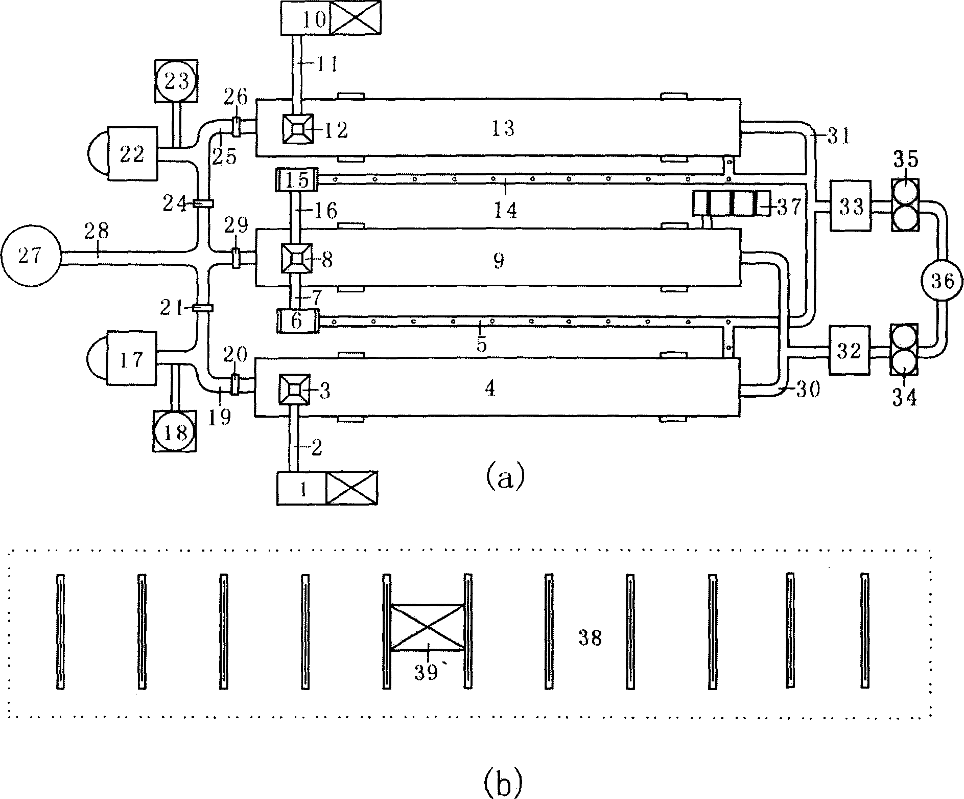
[0015] Such as figure 1 As shown, the sludge drying system using the composite energy of flue gas waste heat and external heating has subsystems such as heating system, sludge pretreatment system, feeding system, sludge drying and granulation system, and dust removal and gas removal.

[0016]The heating system has a first fluidized furnace 17, a second fluidized furnace 22, a first temperature regulator 18, a second temperature regulator 23, a first ventilation duct 19, a second ventilation duct 25, a first damper 20, a second damper 21, The heat energy provided by the third damper 26, the fourth damper 24, the fifth damper 29, the first induced draft fan 27, the flue 28, and the first fluidized fluidized furnace 17 is controlled at 200-400° C. by the first temperature regulator 18, and is controlled by the first temperature regulator 18. The first wind 20 controls the amount of hot air, and sends it into the first rotary drying kiln 4 through the first ventilation duct 19, an...


PUM

PropertyMeasurementUnit
diameteraaaaaaaaaa
diameteraaaaaaaaaa
diameteraaaaaaaaaa

Abstract

A sludge drying system with the combination of fume's afterheat and two external heat sources is composed of heat supply system, sludge pre-treating system, feeding system, sludge drying-granulating system and dusting and degassing system.

Description

technical field [0001] The invention relates to a sludge drying system in which waste heat of flue gas is combined with double external heat supply sources. Background technique [0002] Urban domestic sewage and industrial wastewater must be treated by sewage treatment plants, and can only be discharged after meeting the national sewage discharge standards. This has become a mandatory environmental protection engineering measure. The functions of urban sewage treatment plants have the following two aspects: one is to purify sewage, so that urban domestic sewage and industrial wastewater can be discharged up to standard after treatment; the other is to safely dispose of sludge generated during sewage treatment to prevent sludge from causing secondary environmental pollution. In recent decades, through the continuous introduction and digestion of foreign advanced technology, my country's water treatment technology has become increasingly mature, and all kinds of sewage can g...

Claims


Application Information

Patent Timeline
Patent Type & Authority Applications(China)
IPC IPC(8): C02F11/12
Inventor 翁焕新
Owner ZHEJIANG UNIV
Why Eureka
Try Eureka