Cold-cathode tube lighting device

A cold-cathode tube and lighting device technology, which is applied to lighting devices, components of lighting devices, circuit layout, etc., can solve the problems of difficulty in miniaturization of devices, difficulty in reducing the number of parts, etc., easy to achieve thinning, flame retardant High performance, avoiding the effect of malfunction

Inactive Publication Date: 2007-01-17
PANASONIC CORP
View PDF0 Cites 2 Cited by
  • Summary
  • Abstract
  • Description
  • Claims
  • Application Information

AI Technical Summary

Problems solved by technology

As a result, it is difficult to reduce the number of parts, making further miniaturization of the entire device difficult

Method used


Image

  • Cold-cathode tube lighting device
  • Cold-cathode tube lighting device
  • Cold-cathode tube lighting device

Examples


Embodiment approach 1

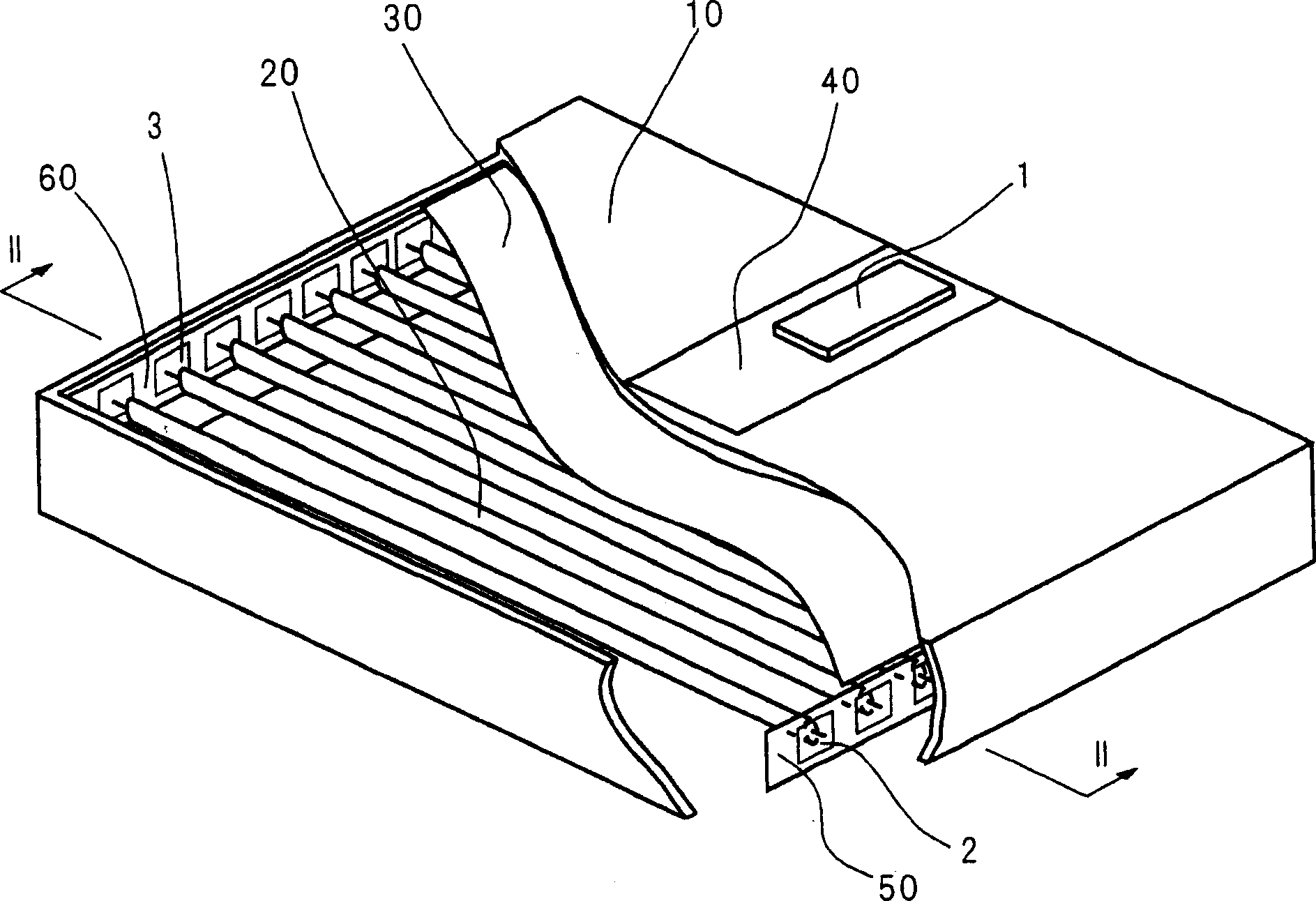
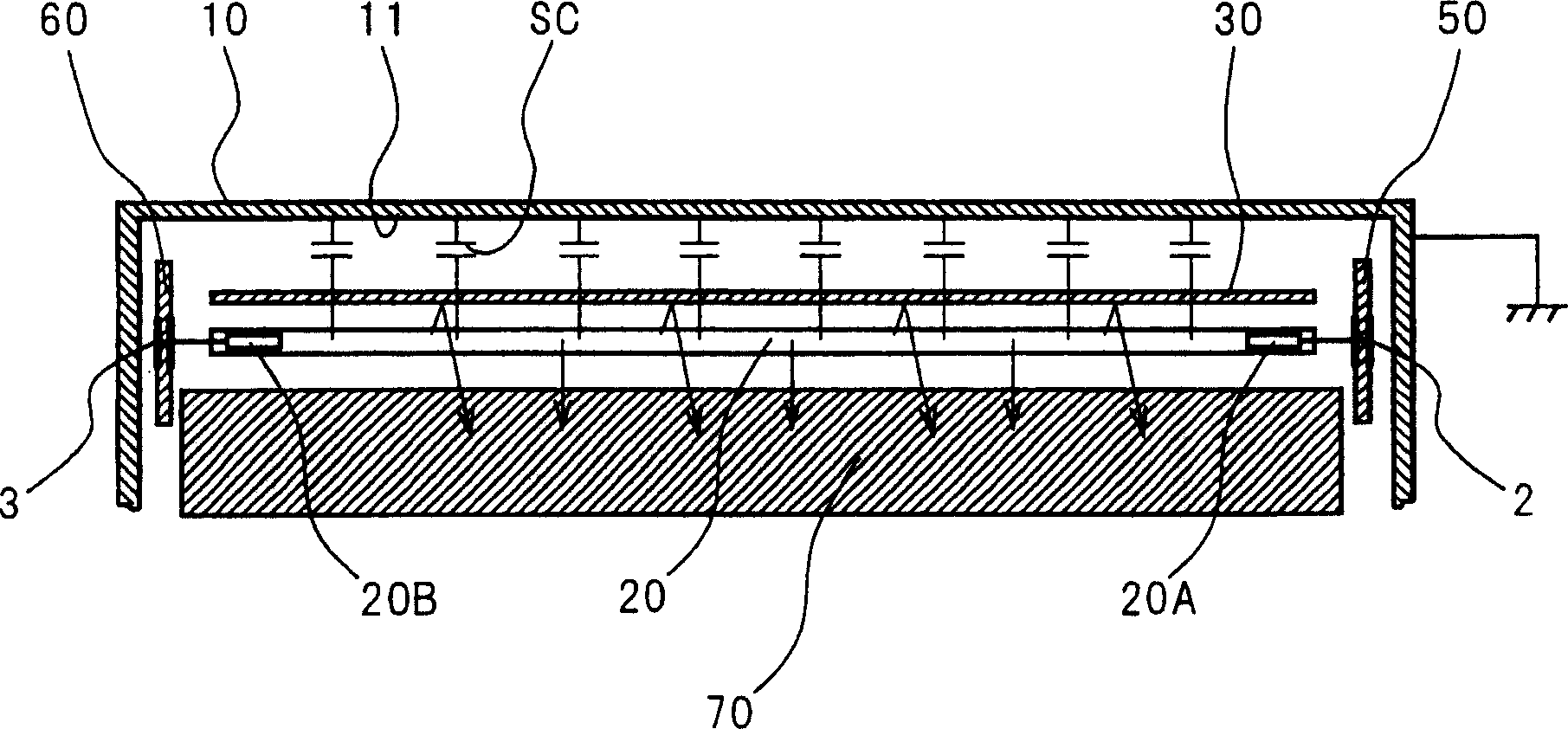
[0070] figure 1 It is a perspective view showing the configuration of a backlight of a liquid crystal display equipped with the cold-cathode tube lighting device according to Embodiment 1 of the present invention. figure 1 , the housing 10 is drawn on its back panel. In addition, in order to show the inside of the housing 10, part of the back panel and side panels of the housing 10 are removed. figure 2 for along figure 1 The profile of the line II-II shown in ( figure 1 The arrows shown in indicate the direction of sight).

[0071] figure 1 and figure 2 The liquid crystal display shown in has a housing 10 , a plurality of cold cathode tubes 20 , a reflector 30 , a first substrate 40 , a second substrate 50 , a third substrate 60 , and a liquid crystal panel 70 . The cold-cathode tube lighting device according to Embodiment 1 of the present invention is mainly divided into three blocks (blocks) 1, 2, and 3, which are mounted on the first substrate 40, the second s...

Embodiment approach 2

[0134] The cold-cathode tube lighting device according to Embodiment 2 of the present invention is incorporated in a liquid crystal display similarly to the device according to Embodiment 1 described above. Since the configuration of this liquid crystal display is the same as that in Embodiment 1 above, the figure 1 and figure 2 And the description in Embodiment 1 above.

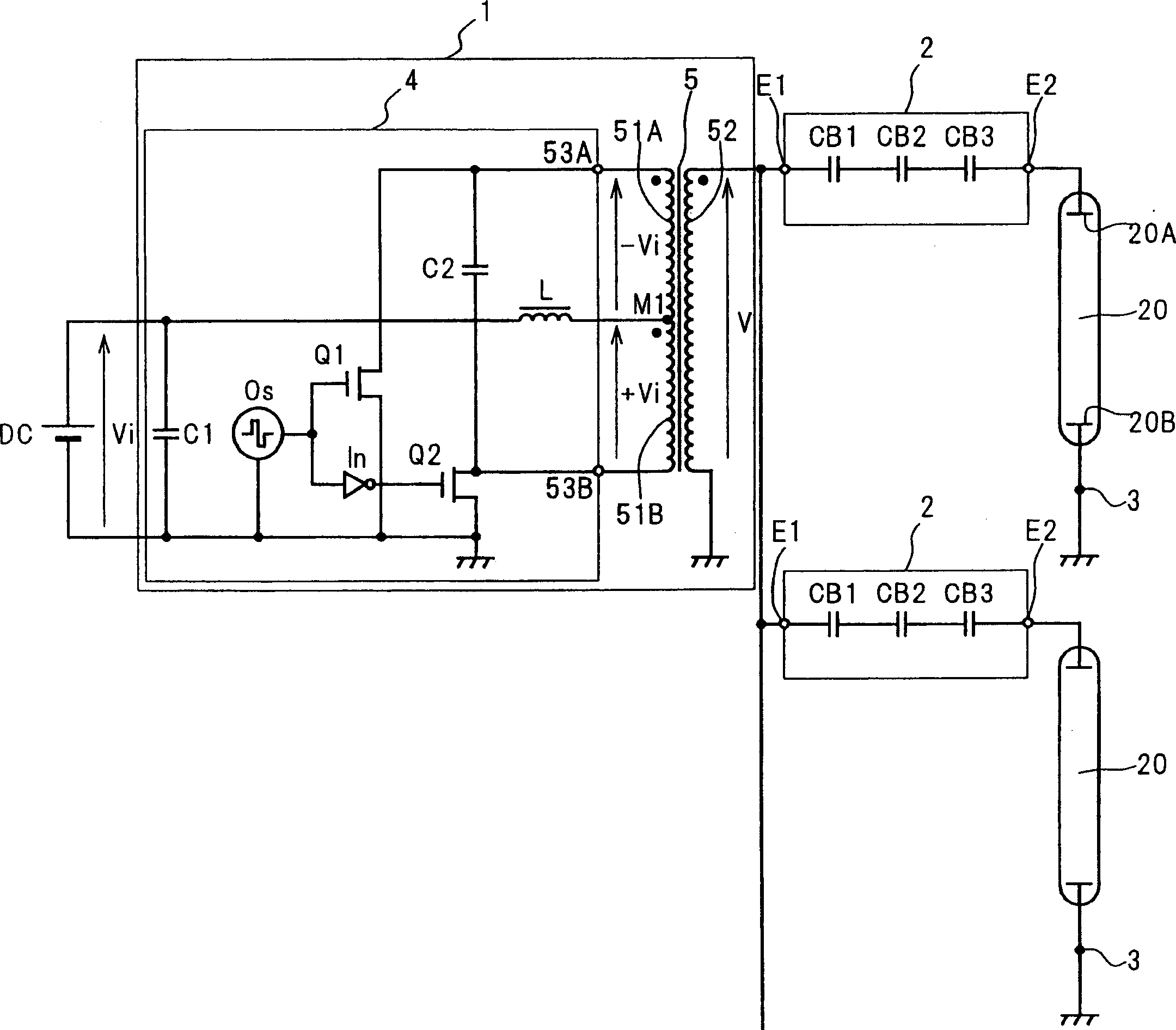
[0135] Figure 17 It is a circuit diagram showing the configuration of a cold-cathode tube lighting device according to Embodiment 2 of the present invention. This cold-cathode tube lighting device has components similar to those of the device in Embodiment 1 except for the configuration of the first module 1 (see image 3 ) have the same components. Therefore, labeling these same constituent elements with image 3 The symbols shown in are the same symbols, and their descriptions refer to the descriptions in Embodiment 1.

[0136] The first module 1 includes an oscillator Os, a high-voltage side powe...

Embodiment approach 3

[0146] The cold-cathode tube lighting device according to Embodiment 3 of the present invention is incorporated in a liquid crystal display similarly to the device according to Embodiment 1 described above. Since the configuration of this liquid crystal display is the same as that in Embodiment 1 above, the figure 1 and figure 2 And the description in Embodiment 1 above.

[0147] Figure 18 It is a circuit diagram showing the configuration of the cold-cathode tube lighting device in Embodiment 3 of the present invention. This cold-cathode tube lighting device has components similar to those of the device in Embodiment 1 except for the configuration of the first module 1 and the third module 3 (see image 3 ) have the same components. Therefore, labeling these same constituent elements with image 3 The symbols shown in are the same symbols, and their descriptions refer to the descriptions in Embodiment 1.

[0148] In the cold-cathode tube lighting device according to E...


PUM


Abstract

The inveniton provides a cold-cathode tube lighting device which uniformly lights up a plurality of cold-cathode tubes with a common power supply and is downsized effectively by using a ballast capacitor. A substrate (50) is divided into as many blocks (2) as the number of cold-cathode tubes (20). Two conductor layers in each block (2) respectively include two foils (21A and 21B, 24A and 24B). The first foil (21A) in the first conductor layer is connected with a common low-impedance power supply. Between the two conductor layers, an area where the first foils (21A and 24A) overlap each other forms a first ballast capacitor (CB1), an area where the first foil (24A) and the second foil (21B) overlap each other forms a second ballast capacitor (CB2), and an area where the second foils (21B and 24B) overlap each other forms a third ballast capacitor (CB3). The second foils (21B and 24B) are connected to the first electrode (21) of a cold-cathode tube (20).

Description

technical field [0001] The invention relates to a cold-cathode tube lighting device, in particular to a device for lighting multiple cold-cathode tubes. Background technique [0002] Fluorescent tubes are roughly classified into hot-cathode tubes and cold-cathode tubes according to their electrode structures. In cold cathode tubes (also called CCFLs), the electrodes are made of a substance that emits many electrons by applying a high voltage. That is, unlike a hot cathode tube, the electrode does not include a filament for thermionic emission. As a result, cold cathode tubes are particularly advantageous in that they have a very small tube diameter, a long life, and low power consumption, compared with hot cathode tubes. Based on these advantages, cold-cathode tubes are mainly used in products that require thinning (or miniaturization) and power saving, such as backlights of liquid crystal displays and light sources of FAX / scanners. [0003] A cold-cathode tube has electr...

Claims


Application Information

Patent Timeline
Patent Type & Authority Applications(China)
IPC IPC(8): H05B41/24G02F1/13357H01F38/10F21V23/02F21Y103/00G02F1/1335H01F27/32H01F38/08H05B41/282
CPCH05B41/2822H01F27/326H01F38/10
Inventor 小松明幸三宅永至川高谦治真锅俊夫
Owner PANASONIC CORP
Why Eureka
Try Eureka