

DC magnetic field sensor
A DC magnetic field and sensor technology, which is applied to the magnitude/direction of the magnetic field and the use of electromagnetic devices for magnetic field measurement, etc., can solve the problems that do not involve the use of magnetoelectric effect sensors, and does not involve the use of magnetoelectric material sensors, etc., and achieves simple structure, Inexpensive and simple to operate
- Summary
- Abstract
- Description
- Claims
- Application Information
AI Technical Summary
Problems solved by technology
Method used
Image

Examples
Embodiment 1
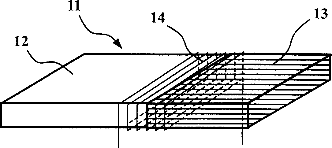
[0023] Embodiment 1, referring to FIG. 1( a ), a DC magnetic field sensor includes a magnetoelectric element 11 and an external induction coil 14 .
[0024] The magnetoelectric element 11 is composed of a PZT piezoelectric ceramic unit 12 and a TbDyFe magnetostrictive alloy unit 13 longitudinally. The shape is rectangular, and the overall size is: 28mm (length) × 6mm (width) × 1mm (thickness). The size of the piezoelectric ceramic unit 12 is: 16mm×6mm×1mm, and the size of the TbDyFe magnetostrictive alloy unit 13 is: 12mm×6mm×1mm. The polarization direction of the PZT piezoelectric ceramic unit 12 is the thickness direction, and the preferred magnetic domain orientation of the TbDyFe magnetostrictive alloy unit 13 is along the length direction. The PZT piezoelectric ceramic unit 12 and the TbDyFe magnetostrictive alloy unit 13 are bonded with an epoxy resin adhesive. The two electrodes of the magnetoelectric element 11 are connected to an alternating current power source (no...
Embodiment 2
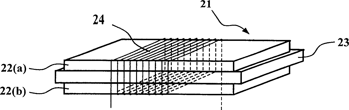
[0027] Example 2, see figure 2 , a DC magnetic field sensor, including a magnetoelectric element 21 and an external induction coil 24 .
[0028] The magnetoelectric element 21 is rectangular and has three layers. The upper and lower layers are PZT piezoelectric ceramic sheets 22(a) and 22(b), and the middle layer is TbFe 2 Magnetostrictive alloy sheet 23. Among them, the polarization direction of the outer two layers of PZT piezoelectric ceramic rectangular sheets 22 (a) and 22 (b) is the thickness direction, and the middle layer of TbFe 2 The preferred magnetic domain orientation of the alloy rectangular sheet 23 is along the length direction. The overall size of the magnetoelectric element is: 18mm (length) × 4mm (width) × 3mm (thickness), among which, TbFe 2 The dimensions of the alloy rectangular sheet 23 and the PZT piezoelectric ceramic rectangular sheets 22 ( a ) and 22 ( b ) are both 18 mm×4 mm×1 mm.
[0029] The external induction coil 24 adopts a copper core ena...
Embodiment 3
[0031] Example 3, see image 3 , a DC magnetic field sensor, including a magnetoelectric element 31 and an external induction coil 33 .
[0032] Magnetoelectric element 31 is NiFe 2 o 4 / PZT particle composite magnetoelectric composite material, in which NiFe2 o 4 The volume content is 0.45. The shape of the magnetoelectric element 31 is a cylinder with an overall size of 10 mm in diameter and 5 mm in thickness. In order to reduce the driving voltage, the cylinder is made of five pieces of NiFe with a diameter of 10 mm and a thickness of 1 mm. 2 o 4 / PZT discs 32 are laminated, and the layers are bonded with epoxy resin adhesive. per NiFe 2 o 4 / PZT wafer 32 is electrically polarized along the thickness direction. The first-order radial resonance frequency of the magnetoelectric element 31 is 350 kHz.
[0033] The induction coil 33 is wound around the periphery of the magnetoelectric element cylinder 31 with a copper core enameled wire with a wire diameter of 0.1 mm....
PUM
 Abstract
Description
Claims
Application Information