Liquid-conveying metallorganics chemical vapour deposition apparatus

A chemical vapor deposition, metal organic technology, applied in gaseous chemical plating, metal material coating process, coating and other directions, can solve problems such as large vapor pressure difference and difficult to control transportation, and achieve instant discharge and large application range. , the effect of avoiding complexity problems

Inactive Publication Date: 2007-03-07
XIAN TECHNOLOGICAL UNIV
View PDF2 Cites 14 Cited by
  • Summary
  • Abstract
  • Description
  • Claims
  • Application Information

AI Technical Summary

Problems solved by technology

[0010] The purpose of the present invention is to overcome the shortcomings of the above-mentioned technology or equipment, solve the problem that traditional MOCVD equipment has a large vapor pressure difference between different ma

Method used


Image

  • Liquid-conveying metallorganics chemical vapour deposition apparatus
  • Liquid-conveying metallorganics chemical vapour deposition apparatus
  • Liquid-conveying metallorganics chemical vapour deposition apparatus

Examples


Embodiment 1

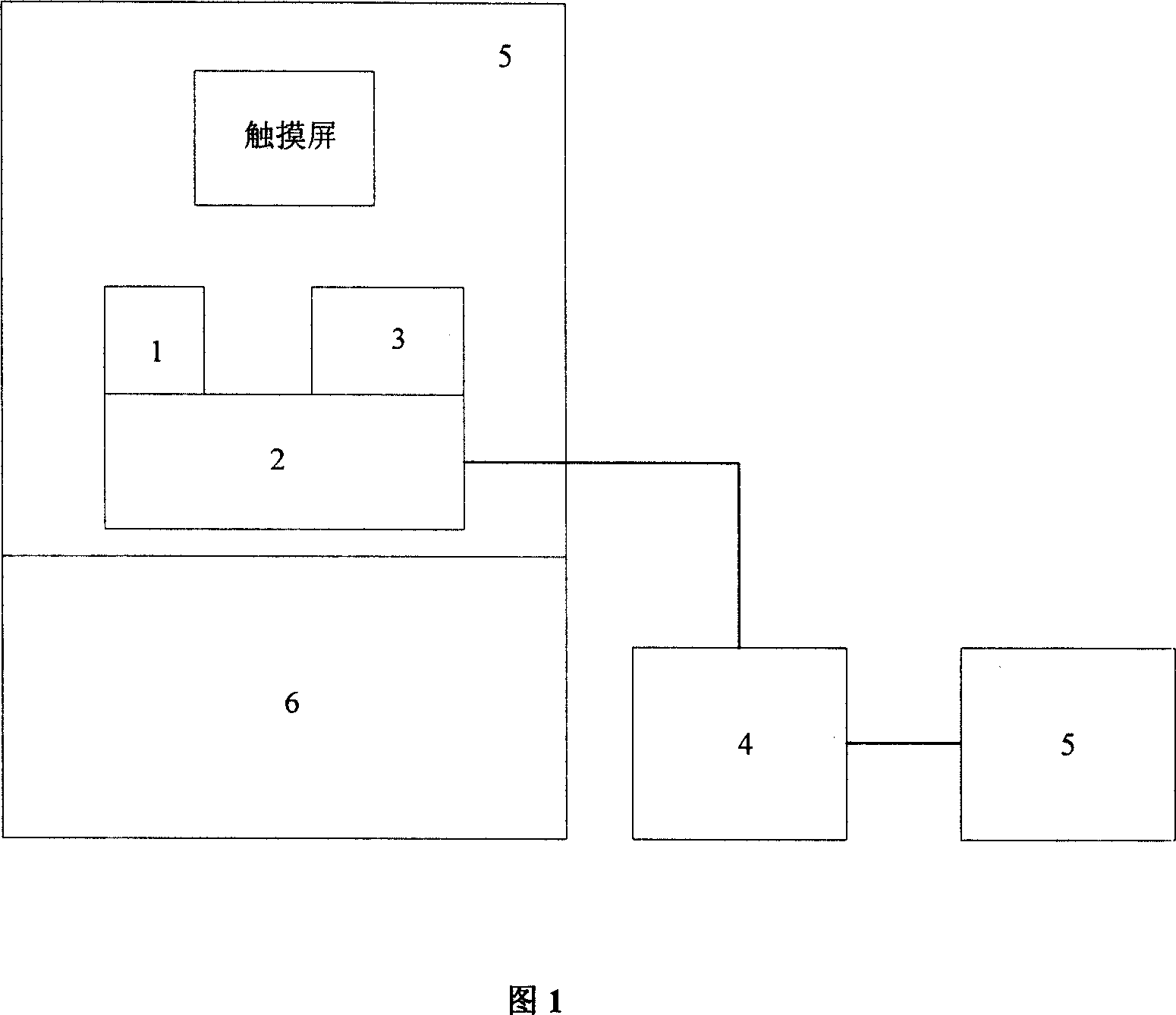
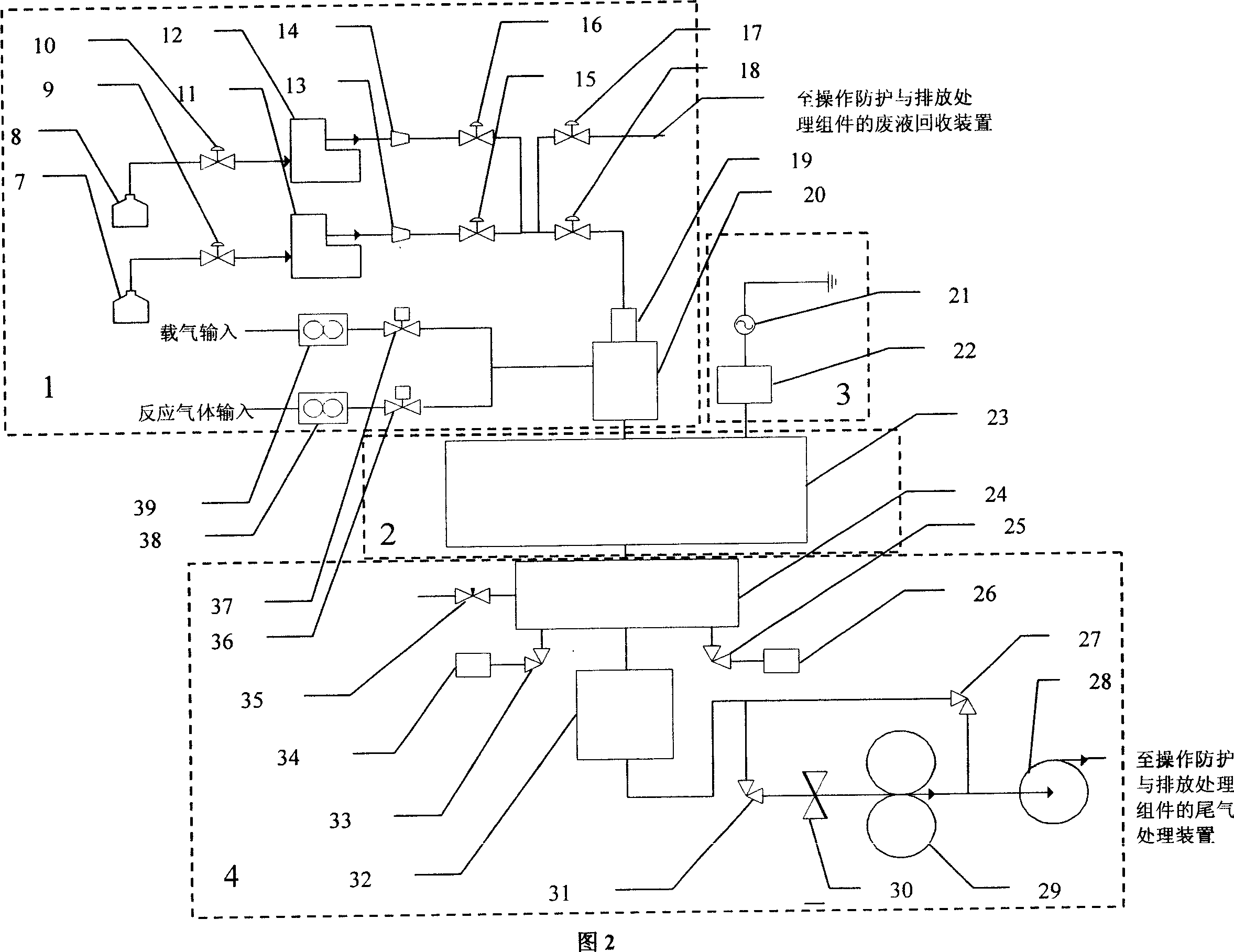
[0033] Embodiment 1: Referring to Fig. 1, the metal-organic chemical vapor deposition equipment for liquid delivery includes a reaction chamber component, a radio frequency discharge plasma component, a vacuum component, an operation protection and emission treatment component, an electric control component, and the radio frequency discharge plasma component passes through The output electrode is connected to the electrode of the gas distribution box of the reaction chamber assembly, the gas output pipe of the reaction chamber assembly is connected to the pneumatic valve of the vacuum assembly, and the exhaust gas output channel of the vacuum assembly is directly connected to the exhaust gas treatment device of the operation protection and emission treatment assembly. The total equipment also includes a multi-component vaporization component 1, which is a replaceable integrated component, mainly composed of multiple liquid source delivery channels, two gas delivery channels, ato...

Embodiment 2

[0037] Embodiment 2: The overall equipment is the same as in Embodiment 1. The vacuum assembly 4 of the present invention also includes a powder catcher 32. The powder catcher 32 is composed of an upper part 58 of the catcher and a lower part 63 of the catcher which can be easily disassembled. The upper and lower parts of the catcher are fastened and loosened. The powder catcher 32 is a cylindrical structure. The outer wall of the cylinder is fixed with a cooling device 66. The upper end of the powder catcher 32 is connected to the reaction chamber assembly 2 through the gas storage cylinder 24. It is divided into two paths, one path is connected to the dry pump 28 through the DN25 angle valve 27, and the other path is connected to the Roots pump 29 through the DN50 angle valve 31.

[0038] The cooling device 66 is made of a stainless steel tube that is evenly wound and welded on the outer wall of the cylinder, and liquid nitrogen is injected into the upper part 58 of the catch...

Embodiment 3

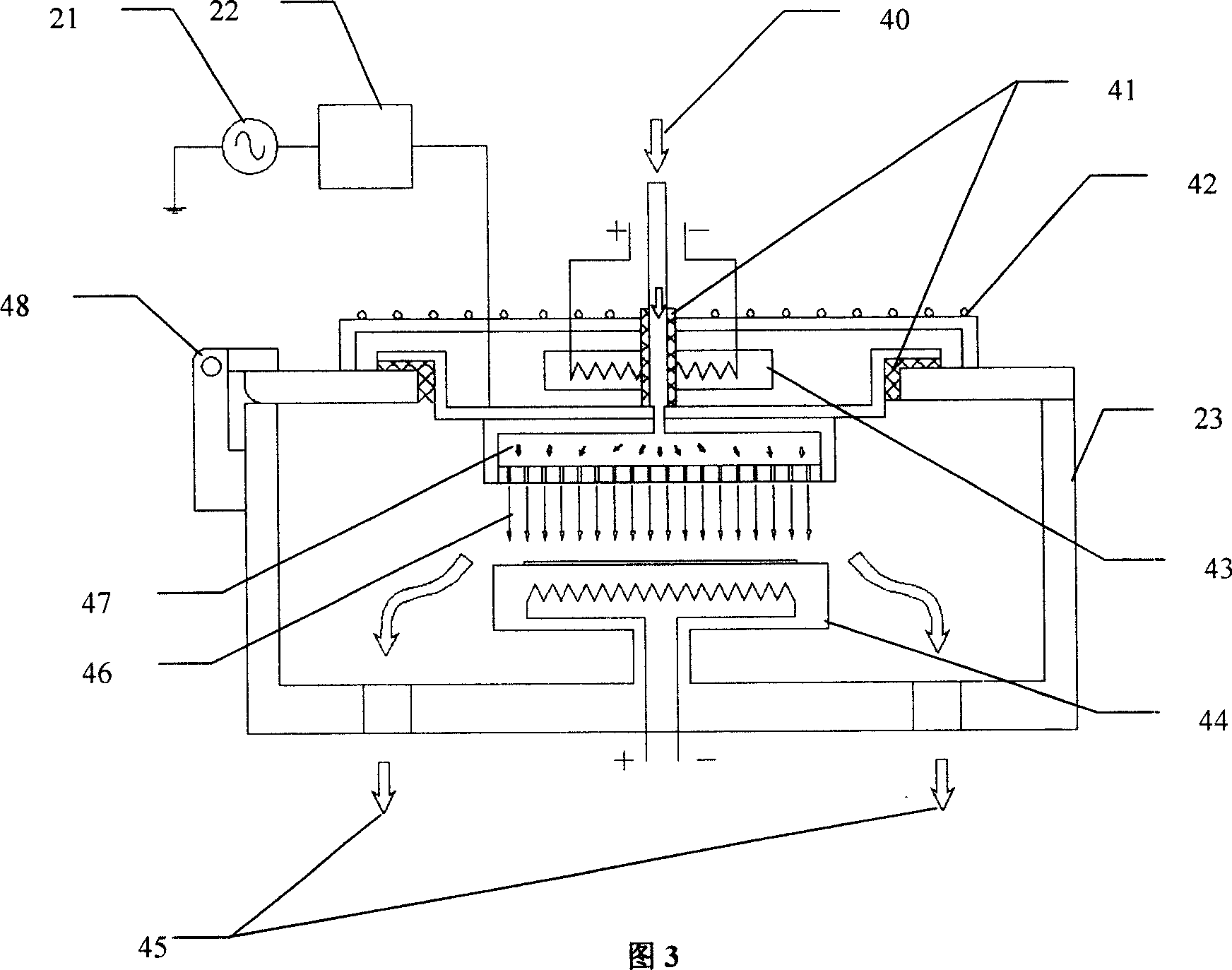
[0039] Embodiment 3: overall equipment is the same as embodiment 2, referring to Fig. 3, the upper and lower electrodes in the reaction chamber assembly 2 are adjustable spacing electrodes, that is, the upper electrode flat plate connected to the radio frequency discharge plasma assembly 3 is served by the gas distribution box 47, and the gas distribution Small holes are evenly distributed on the bottom of the box 47. The lower electrode is formed by the substrate table 44. The distance between the two electrodes is adjusted by increasing or decreasing the number of backing plates. The backing plate is in close contact with the upper electrode and has a constant thickness.


PUM


Abstract

The invention discloses a metal organic chemical gas-phase sedimentary equipment transmitted by liquid, which comprises the following parts: multi-element gasifying component, reacting chamber, RF discharge plasmid, vacuum component, operational prevention and draining disposing component and electric control component, wherein the multi-element gasifying component is composed of multi-path liquid transmission channels, two-path gas transmission channel, atomizer, carburetor, valve and pipe; the liquid is atomized and carbureted, which is transmitted into reacting chamber to react with gas to produce needed oxide; the sediment forms film on the substrate, whose temperature is controllable; the electric control component realizes self-control of whole technology through programmable controller PLC.

Description

technical field [0001] The invention belongs to the technical field of chemical vapor deposition growth, in particular to a chemical vapor deposition equipment for liquid conveying metal organics. Background technique [0002] Metal Organic Chemical Vapor Deposition (MOCVD) is a technology for preparing high-quality epitaxial films. The prepared epitaxial films are mainly used in optoelectronic, semiconductor and microwave devices, and are also used in the preparation of ultra-large-scale integrated circuits. related to chip technology. Since it was first proposed in the 1960s, after the development from the 1970s to the 1980s, it has become the core growth technology for the preparation of epitaxial wafers of optoelectronic materials such as gallium arsenide and indium phosphide in the 1990s, especially for the preparation of gallium nitride light-emitting diodes and lasers. Mainstream method for epiwafers. So far, no other method can compare with it in terms of the main ...

Claims


Application Information

Patent Timeline
IPC IPC(8): C23C16/18C23C16/52
Inventor 刘卫国周顺高爱华张伟
Owner XIAN TECHNOLOGICAL UNIV
Why Eureka
Try Eureka