Exhaust gas purifying device of internal combustion engine

An exhaust gas purification device and internal combustion engine technology, applied in exhaust devices, internal combustion piston engines, noise reduction devices, etc., can solve the problems of inability to send out air from the reductant injection device, increase of particles and unburned fuel, and difficulty in reaction, etc., to achieve suppression Generation of particulates and discharge of unburned fuel, good spray state, and effects of eliminating waste

Inactive Publication Date: 2007-03-28
KOMATSU LTD
View PDF2 Cites 4 Cited by
  • Summary
  • Abstract
  • Description
  • Claims
  • Application Information

AI Technical Summary

Problems solved by technology

[0009] However, according to Patent Document 2, since the supercharger side of the exhaust turbocharger and the reducing agent spraying device are simply communicated through the air extraction passage, if the engine is operated in a low-load region, the exhaust turbine In the state where the pressure ratio of the supercharger is low and the air flow rate is also small, the air cannot be sufficiently sent to the reducing agent injection device, the reducing agent is difficult to be atomized, and the NO can n

Method used


Image

  • Exhaust gas purifying device of internal combustion engine
  • Exhaust gas purifying device of internal combustion engine
  • Exhaust gas purifying device of internal combustion engine

Examples


no. 1 approach

[0053] 〔1-1〕Overall composition

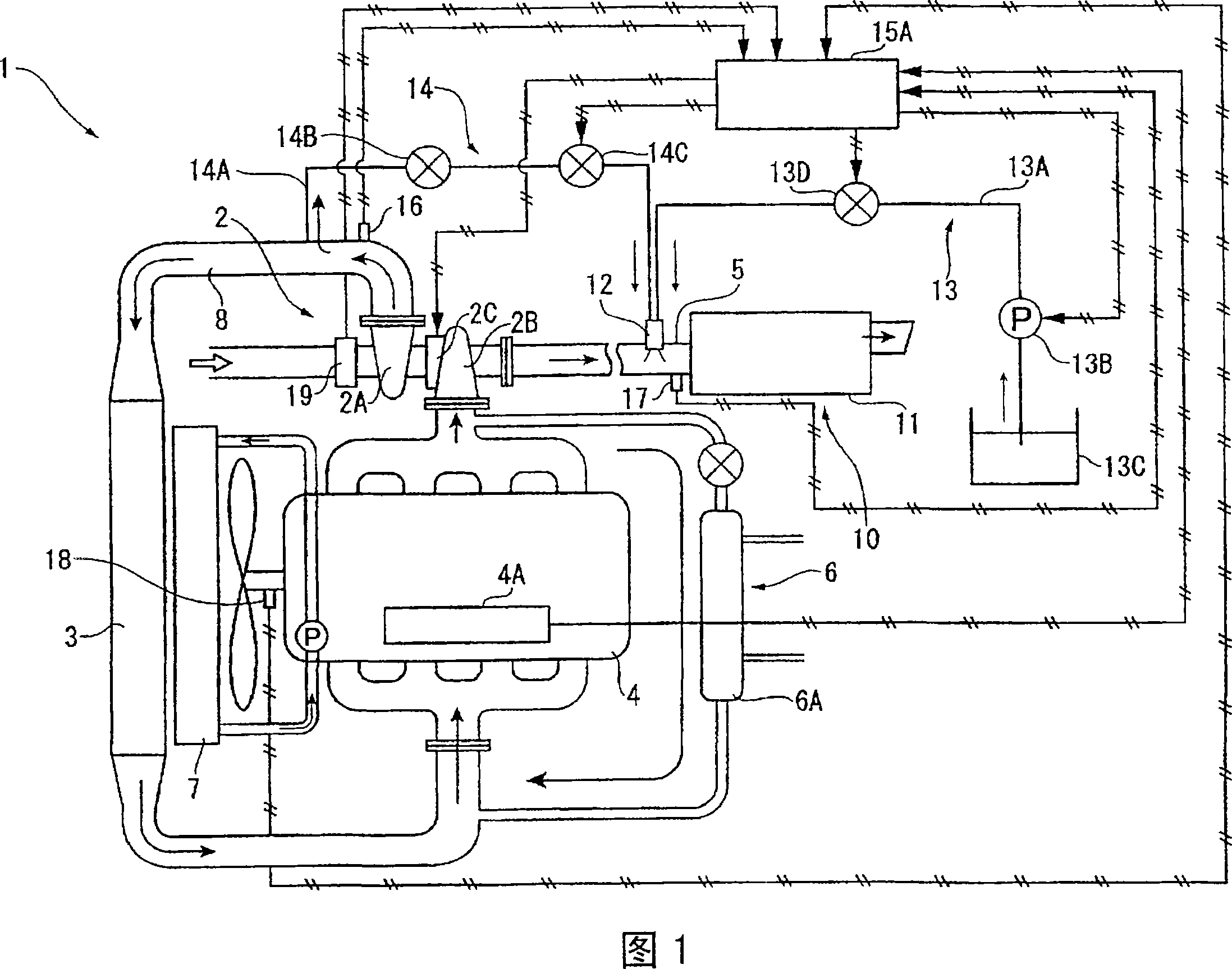
[0054] FIG. 1 is a schematic view showing one revolution of a diesel engine (internal combustion engine) equipped with an exhaust gas purification device 10 according to a first embodiment of the present invention.

[0055] A diesel engine (hereinafter simply referred to as an engine) 1 includes a variable exhaust turbocharger 2 . The supercharged air from the supercharger 2A side of the variable exhaust turbocharger 2 is supplied to the engine main body 4 through an after cooler 3, and the exhaust gas from the engine main body 4 is cooled by the variable exhaust turbocharger. The compressor 2B of 2 rotates and discharges through the exhaust gas passage 5.

[0056] In addition, in the engine 1 of this embodiment, an EGR (Exhaust Gas Recirculation) device 6 is provided, and a part of the exhaust gas returned from the exhaust manifold to the intake manifold suppresses the concentration of oxygen in the combustion chamber, and the combustion is ...

no. 2 approach

[0118] Next, a second embodiment of the present invention will be described. In addition, in the following description, the same part as what has already been explained is given the same code|symbol, and abbreviate|omits or abbreviates description.

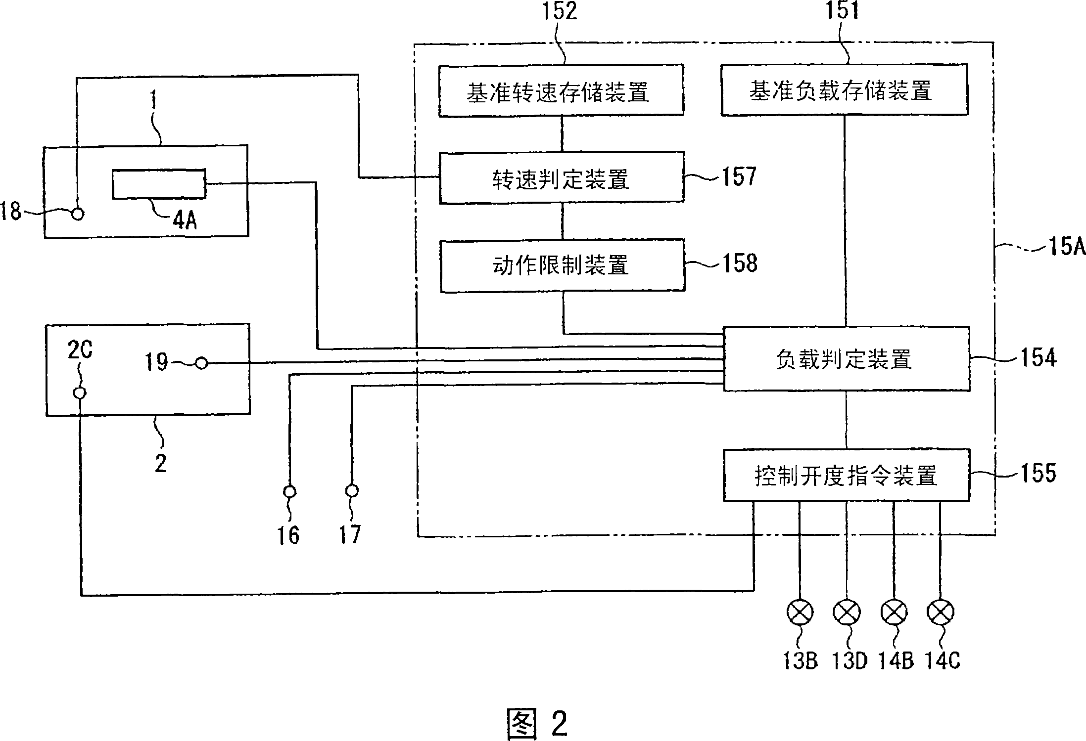
[0119] In the above-mentioned first embodiment, feedback control is performed, and the control of adjusting the nozzle opening is adopted according to the detection results of loads such as combustion injection amount, boost pressure, and exhaust temperature, and the rotational speeds of the engine and the variable exhaust turbocharger. method.

[0120] In contrast, in the second embodiment, the opening degree is uniquely controlled using the opening degree control pattern stored in the opening degree control pattern storage device 153 according to the fuel injection amount and the engine speed without feedback control, that is, the so-called Feedforward control is different from the first embodiment.

[0121] First, the structu...

no. 3 approach

[0133] FIG. 7 shows an exhaust gas purification device 10 according to a third embodiment of the present invention. In this embodiment, an air tank 14D is provided between the outlet side of the supercharger 2A and the on-off valve 14C on the air take-out passage 14A, and an air tank 14D is provided between the air tank 14D and the outlet side of the supercharger 2A. The difference from the first embodiment is that the pressure control valve 14E is not a check valve. Other configurations and control methods are the same as those of the first embodiment.

[0134] Furthermore, the air tank 14D of the present embodiment functions as an accumulator for storing air pressure for supplying to the reducing agent spraying device 12 . In addition, the pressure control valve 14E, when the accumulated pressure of the air tank 14D reaches a predetermined value or more, opens the air take-out passage 14A on the upstream side thereof, so that the air sent from the supercharger 2A side is re...


PUM


Abstract

An exhaust emission control device of an internal combustion engine capable of satisfactorily atomizing a reducing agent and surely securing combustion air. Since the controller of the exhaust emission control device controls the nozzle opening of a variable discharge turbo for spraying urea water, even when the engine is in a low load area of T1 to T2 and a supercharging pressure does not rise normally, the supercharging pressure P suitable for spraying the urea water can be provided by controlling the nozzle opening of the variable discharge turbo so as to be closed more than a normal one (chain double-dashed line), and the urea water can be securely atomized by a part of the supercharging air. Also, since the amount of combustion air supplied to the engine is increased by raising the supercharging pressure to P, satisfactory combustion can be realized and the generation of particulates and the discharge of unburned fuel can be suppressed.

Description

[0001] technology area [0002] The present invention relates to an exhaust gas purifying device for an internal combustion engine, and in particular, to an exhaust gas purifying device that is installed in an exhaust gas passage of an internal combustion engine with a variable exhaust turbocharger and purifies exhaust gas by supplying a reducing agent. Background technique [0003] Currently, it is known that in order to collect particulates (particulate matter) in exhaust gas discharged from internal combustion engines such as diesel engines and reduce NO X amount, and an exhaust gas purification device is installed in the exhaust gas passage of the internal combustion engine. [0004] As an exhaust gas purification device that collects particulates, a device equipped with a diesel particulate filter (DPF: Diesel Particulate Filter) is being developed as a means of reducing NO X (nitrogen oxides) exhaust gas purification device, equipped with NO X Reduction catalyst and NO...

Claims


Application Information

Patent Timeline
IPC IPC(8): F01N3/08B01D53/94F01N3/04F02B37/00F02B37/24F02D23/00F01N3/20F02M25/14
CPCB01D53/9431F02B29/0425F02B37/24Y02T10/144F02M25/0727F02M25/14B01D2251/2067F02D41/0007F02D23/00Y02T10/24Y02T10/121F01N3/2066F02M25/0707F01N2610/02F02M26/05F02M26/23Y02T10/12F01N3/04F01N3/08F01N3/10F01N3/20
Inventor 西山利彦佐藤浩树
Owner KOMATSU LTD
Why Eureka
Try Eureka