Aluminum material, method of manufacturing aluminum material , electrolytic capacitor and anode material

A technology for electrolytic capacitors and aluminum materials, applied in electrolytic capacitors, capacitors, anodizing and other directions, can solve the problems of difficult to uniformly remove the surface layer, difficult to etch characteristics of aluminum materials, and to increase capacitance.

Inactive Publication Date: 2010-10-06
SHOWA DENKO KK
View PDF11 Cites 0 Cited by
  • Summary
  • Abstract
  • Description
  • Claims
  • Application Information

AI Technical Summary

Problems solved by technology

[0020] However, when the surface layer is chemically removed, it is difficult to uniformly remove the surface layer because the surface of the aluminum material has uneven corrosion resistance before removing the surface layer, thus limiting the increase in capacitance
[0021] With the technique described in Patent Document 3, since the surface layer of the aluminum material is not uniform before washing, the surface layer of the aluminum material is not uniformly dissolved, making it difficult to obtain improved etching characteristics of the aluminum material after final annealing
[0022] Through the technology described in Patent Document 4, although heating oxidation before annealing is beneficial to the uniformity of the surface layer of the aluminum material, the characteristics of the surface layer of the aluminum material before removal are not uniform, thereby affecting the surface after washing, so by heating Oxidation is insufficient to improve uniformity and limits the increase in capacitance
[0023] In addition, although the characteristics of the oxidized surface of the aluminum material after the intermediate annealing are changed by the atmosphere in the intermediate annealing, which mainly affects the subsequent surface layer removal, there is no description about the intermediate annealing atmosphere in Patent Document 5

Method used


Image

  • Aluminum material, method of manufacturing aluminum material , electrolytic capacitor and anode material
  • Aluminum material, method of manufacturing aluminum material , electrolytic capacitor and anode material
  • Aluminum material, method of manufacturing aluminum material , electrolytic capacitor and anode material

Examples


example 1-1

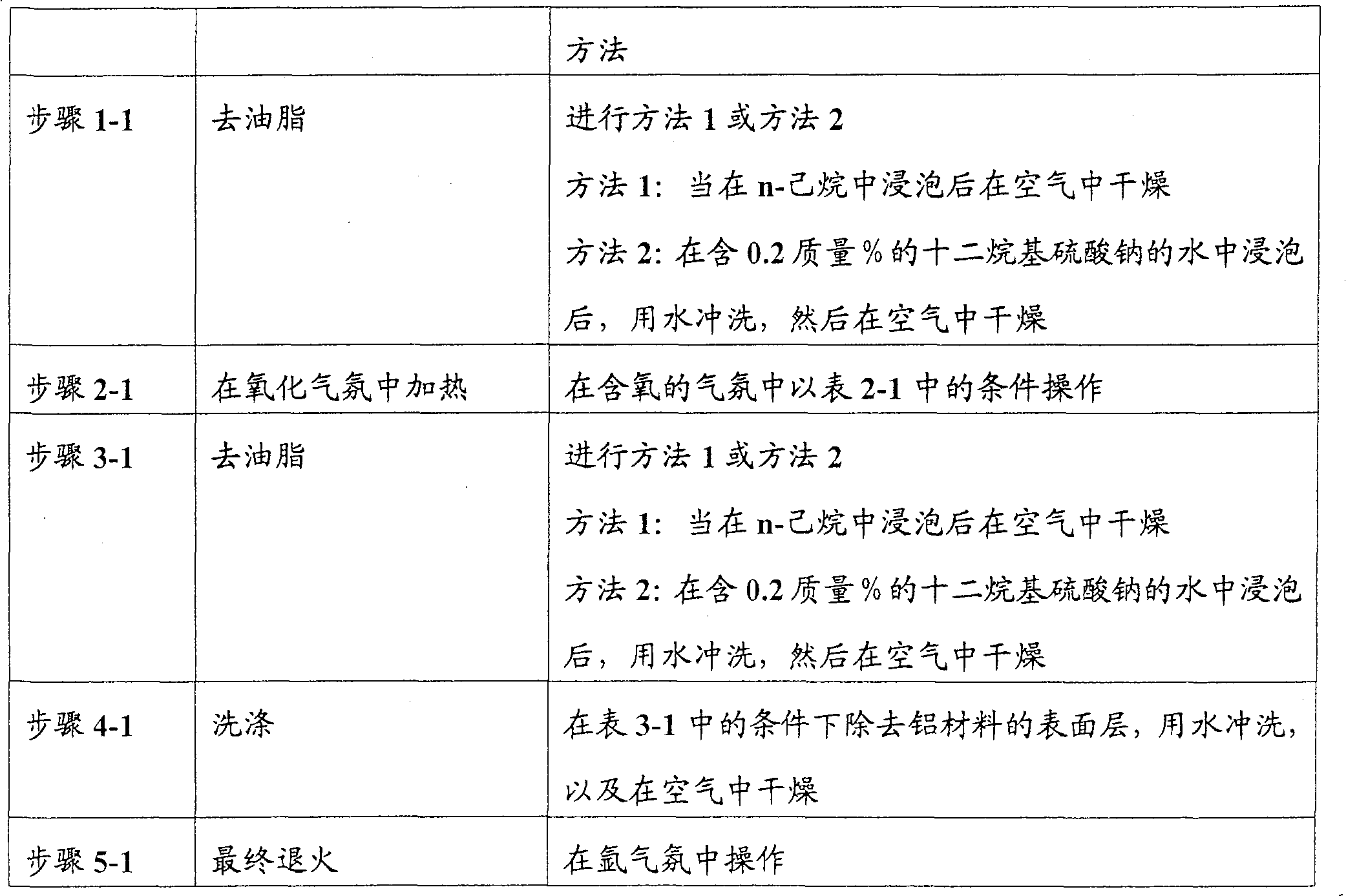
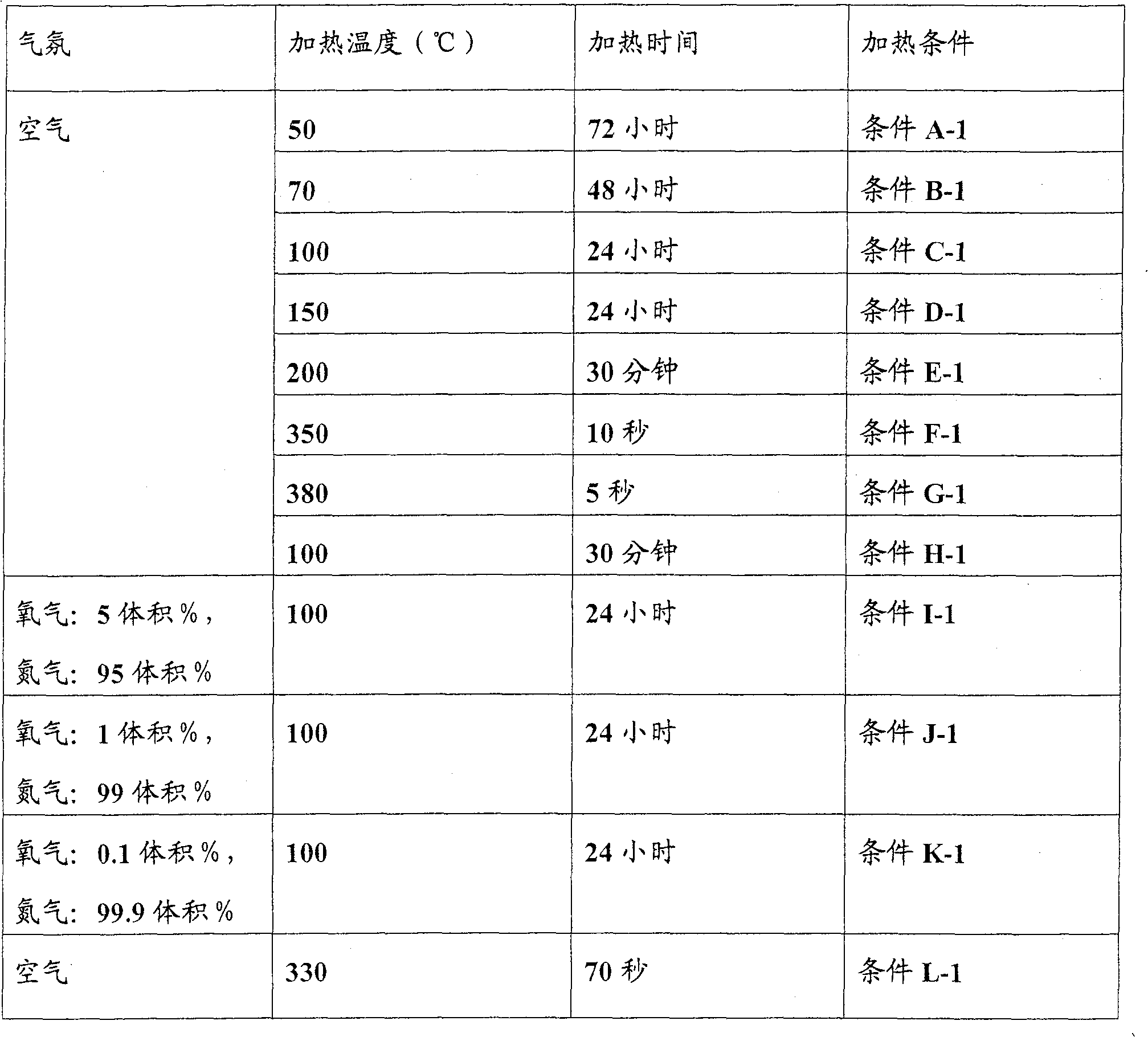
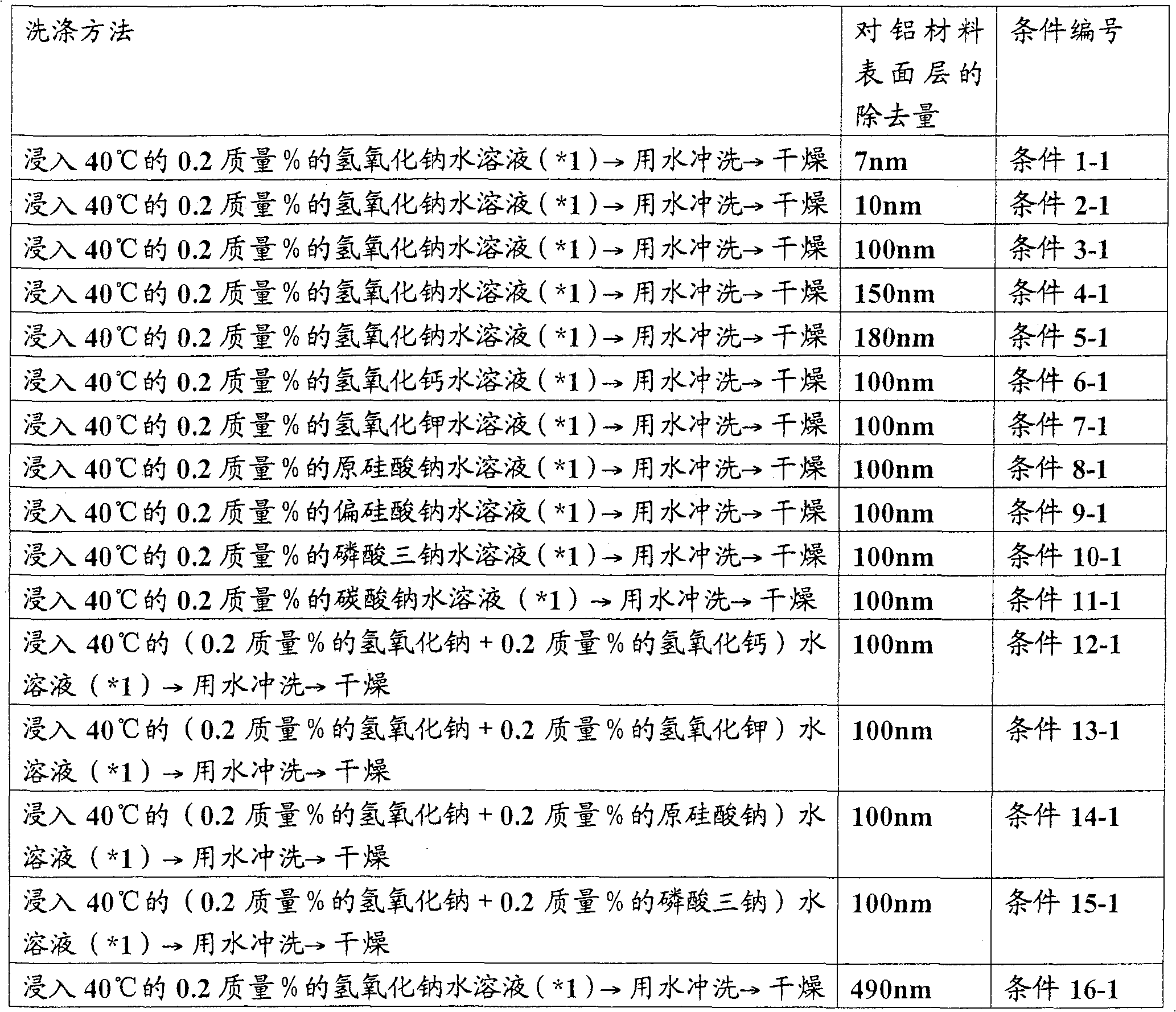
[0360] The aluminum block is subjected to hot rolling, cold rolling, intermediate annealing and finish cold rolling in sequence. As shown in Table 5-1, the obtained flake aluminum material having a thickness of 110 μm and a purity of 99.99% was degreased using n-hexane (step 1-1). After heating at 150° C. in air for 24 hours (step 2-1), by immersing in 20% by mass sulfuric acid solution at 80° C., an average 10 nm surface layer of the aluminum material was removed (step 4-1). Then, the material was subjected to final annealing (step 5-1) at 540° C. for 4 hours in an argon atmosphere to obtain an aluminum material for an electrode of an electrolytic capacitor.

example 2-1 to example 49-1

[0361] Example 2-1 to Example 49-1, Comparative Example 1-1 to Comparative Example 3-1

[0362] Under the conditions shown in Tables 5-1 to 7-1, aluminum materials for electrolytic capacitor electrodes were obtained.

[0363] The aluminum material obtained in each example and comparative example was immersed in HCL containing 1.0 mol / liter and 3.5 mol / liter H 2 SO 4 in an aqueous solution, wherein the temperature of the solution is 75°C. At the same temperature, using solutions with the same composition, at 0.2A / cm 2 The current density is applied to the material for direct current electrode etching.

[0364] The electrolytically treated aluminum material was further immersed in a mixed solution of 90° C. hydrochloric acid-sulfuric acid having the same composition for 360 seconds, and then an etched foil with larger diameter pits was obtained. The obtained etched foil was dielectrically formed by anodizing at a forming voltage of 270 V according to EIAJ standards, thereby ...

example 1-2

[0434] The aluminum ingots in Table 1-2 having 0.0015 mass % Fe, 0.0022 mass % Si, and 0.0055 mass % Cu (composition 3-2) were hot rolled. Aluminum materials having a thickness of 130 µm obtained by processing the plates obtained by cold rolling under the conditions shown in Table 6-2. That is, intermediate annealing (step 2-2) was applied at 260° C. for 18 hours in air. Then, finish cold rolling with a reduction of 20% was performed (step 5-2). After finish cold rolling, degrease the aluminum material with n-hexane (step 6-2), and then remove the 12nm surface layer of the aluminum material by immersing in 20% by mass phosphoric acid aqueous solution at 80°C (step 7-2). Then, the aluminum material was subjected to final annealing at 530° C. for 6 hours in an argon atmosphere (step 8-2) to obtain an aluminum material for an electrode of an electrolytic capacitor.


PUM

PropertyMeasurementUnit
densityaaaaaaaaaa
thicknessaaaaaaaaaa
thicknessaaaaaaaaaa

Abstract

A method for manufacturing an aluminum material for electrolytic capacitor electrodes of the present invention, comprising the steps of heating an aluminum material in an oxidative atmosphere, removing the surface layer of the aluminum material by washing the heated aluminum material and subjecting the washed aluminum material obtained by washing to final annealing.

Description

[0001] Priority is claimed from the following applications: Japanese Patent Application 2004-040328 filed on February 17, 2004, Japanese Patent Application 2004-304717 filed on October 19, 2004, Japanese Patent Application 2004-2004 filed on October 29, 2004 316592, Japanese Patent Application 2004-348837 filed December 1, 2004, Japanese Patent Application 2004-377539 filed December 27, 2004, U.S. Provisional Application 60 / 614,328 filed September 30, 2004, 10, 2004 US Provisional Application 60 / 621,067, filed November 25, and US Provisional Application 60 / 629,971, filed November 23, 2004, the contents of which are incorporated herein by reference. [0002] Cross References to Related Applications [0003] This application is filed under 35 U.S.C. §111(a) and requires U.S. Provisional Application 60 / 614,328, 2004, filed September 30, 2004 under 35 U.S.C. §111(b) under 35 U.S.C. §119(e)(1) Priority dates for US Provisional Application 60 / 621,067, filed October 25, 2004, and US P...

Claims


Application Information

Patent Timeline
Patent Type & Authority Patents(China)
IPC IPC(8): H01G9/055C22F1/04C23G1/22C23F1/20C23F1/36C25D11/04
Inventor 西森秀树穗积敏加藤丰
Owner SHOWA DENKO KK
Why Eureka
Try Eureka