Method for simultaneously determining reflectivity of high reflection cavity mirror and detection mirror

A technology of reflectivity and high reflection, which is applied in the direction of testing optical performance and scattering characteristic measurement, can solve the problems of measurement efficiency and precision limitation, and achieve the effect of reducing measurement steps, improving efficiency and improving measurement accuracy

Inactive Publication Date: 2007-04-11
INST OF OPTICS & ELECTRONICS - CHINESE ACAD OF SCI
View PDF2 Cites 16 Cited by
  • Summary
  • Abstract
  • Description
  • Claims
  • Application Information

AI Technical Summary

Problems solved by technology

The measurement efficiency and accuracy of this method are limited due to the necessity to measure and cancel the system response

Method used


Image

  • Method for simultaneously determining reflectivity of high reflection cavity mirror and detection mirror
  • Method for simultaneously determining reflectivity of high reflection cavity mirror and detection mirror
  • Method for simultaneously determining reflectivity of high reflection cavity mirror and detection mirror

Examples


Embodiment Construction

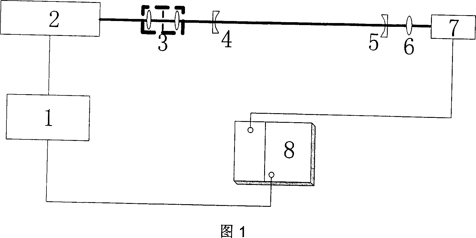
[0014] As shown in Figure 1, measuring device of the present invention is made up of function generator 1, light source 2, spatial filtering and telescopic system 3, plano-concave high reflection mirror 4,5, converging lens 6, detector 7 and lock-in amplifier 8 . Thick lines represent the optical path, and thin lines represent the connection of signal lines. The function generator 1 has two outputs, one output is connected to the light source 2 for square wave modulation of the laser output light intensity, and the other output is connected to the lock-in amplifier 8 as a reference signal. The frequency of the square wave modulation signal can be changed by adjusting the frequency of the function generator. The light source 2 is a modulatable semiconductor laser. Spatial filtering and telescopic system 3 consists of two lenses and a pinhole, which shapes the incident laser beam into a fundamental mode and matches it with the optical cavity mode. Two identical plano-concave ...


PUM


Abstract

The method of determining the reflectivity of high reflectivity cavity lens and testing mirror simultaneously includes the following steps: projecting strength modulated continuous laser beam to a stable resonator comprising two high reflectivity plane-concave cavity lenses and measuring the amplitude and phase of the first harmonic of the optical cavity output signal; maintaining the cavity length unchanged, adding high reflectivity testing mirror to constitute folding cavity and repeating the foregoing step to obtain the amplitude and phase in corresponding frequency; obtaining the amplitude ratio and phase difference of the corresponding frequency; and obtaining the fitting curve of the amplitude ratio and phase difference to modulation frequency or calculating in two frequency points to obtain the reflectivity of the cavity lens and the reflectivity of the testing mirror. The present invention has high measurement efficiency and high measurement precision.

Description

technical field [0001] The invention relates to a method for measuring optical element parameters, in particular to a method for simultaneously determining the reflectivity of a cavity mirror and a test mirror. Background technique [0002] The wide use of high reflectivity optical components in laser systems urgently requires accurate measurement of high reflectivity, while traditional methods, such as spectrophotometers, cannot meet the measurement accuracy requirements of high reflectivity. "A method for measuring the high reflectivity of mirrors", Chinese patent application number 98114152.8, publication number CN1242516A, date of publication: January 26, 2000 and "Precise measurement of high reflectivity of COIL cavity mirrors by compound ring-down optical cavity technology", strong Laser and Particle Beam, Sheng Xinzhi, Sun Fuge, etc., Vol. 10, No. 2, pp. 199-202, May 1998, provided a high reflectivity measurement method, which uses pulsed laser as light source and com...

Claims


Application Information

Patent Timeline
Patent Type & Authority Applications(China)
IPC IPC(8): G01M11/02G01N21/55
Inventor 龚元李斌成
Owner INST OF OPTICS & ELECTRONICS - CHINESE ACAD OF SCI
Why Eureka
Try Eureka