
Cathode for fuel cell and process of the same

A fuel cell and cathode technology, which is applied in the direction of fuel cells, fuel cell parts, solid electrolyte fuel cells, etc., can solve the problem that the power generation performance of fuel cells cannot be improved, fuel cells cannot be used, and oxygen ion conductivity and electron conductivity are not good. Sufficient and other issues, to achieve the effect of improving the conductivity of oxygen ions, improving the performance of power generation, and improving the performance of electrons

Inactive Publication Date: 2007-04-11
TOYOTA JIDOSHA KK
View PDF0 Cites 5 Cited by
  • Summary
  • Abstract
  • Description
  • Claims
  • Application Information

AI Technical Summary

Problems solved by technology

[0009] However, even if the above-mentioned oxygen ion / electron mixed conductor has sufficient oxygen ion conductivity and electron conductivity at a temperature of 800°C or higher, there is a problem that the oxygen ion conductivity in the middle temperature range of, for example, 200 to 600°C and insufficient electron conductivity
[0010] Therefore, a cathode having an oxygen ion / electron mixed conductor cannot be used for a fuel cell in the middle temperature range whose operating temperature ranges from 200 to 600° C., and the power generation performance of the fuel cell cannot be improved

Method used


Image

  • Cathode for fuel cell and process of the same
  • Cathode for fuel cell and process of the same
  • Cathode for fuel cell and process of the same

Examples


Embodiment 1

[0070] In Example 1, using Bi 1.5 Dy 0.5 o 3 As composite oxide B, La 0.5 Sr 0.5 MnO 3 As the inorganic material A, as the oxygen dissociation promoting catalyst C, Pt was used. Bi used as composite oxide B 1.5 Dy 0.5 o 3 As shown in Figure 9, it has at least 10 -2 Oxygen ion conductivity (S / cm).

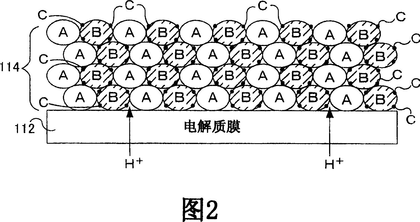
[0071] The oxygen dissociation-promoting catalyst C is first supported on the composite oxide B before being mixed with the inorganic material A as described in the method of manufacturing the cathode 114 described above. Using chloroplatinic acid solution in Bi 1.5 Dy 0.5 o 3 The powder was loaded with 0.5% by weight of Pt. Mix the platinum support Bi in a 1:1 (by volume) ratio using a mortar and pestle 1.5 Dy 0.5o 3 and La 0.5 Sr 0.5 MnO 3 , mix it with a binder and a solvent, and pass the mixture through a roll crusher to obtain a paste. The resulting paste was screen printed onto the electrolyte membrane and dried at 90°C. The paste was screen-printed and dr...

Embodiment 2

[0074] In the example, using La 0.7 Sr 0.3 Ga 0.7 Fe 0.3 o 3 As composite oxide B, La 0.5 Sr 0.5 MnO 3 As the inorganic material A, as the oxygen dissociation promoting catalyst C, Pt was used. La used as composite oxide B 0.7 Sr 0.3 Ga 0.7 Fe 0.3 o 3 As shown in Figure 9, it has at least 10 -2 Oxygen ion conductivity (S / cm).

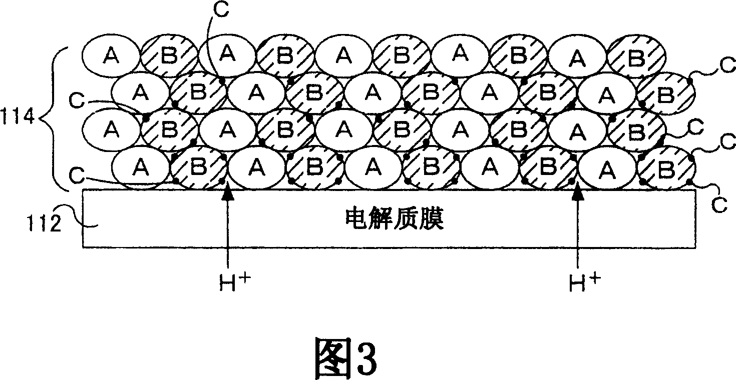
[0075] In Example 2, the oxygen dissociation-promoting catalyst C is supported after mixing the composite oxide B and the inorganic material A, unlike the above-mentioned method of manufacturing the cathode 114 . Mix La in a 1:1 (by volume) ratio using a mortar and pestle 0.7 Sr 0.3 Ga 0.7 Fe 0.3 o 3 and La 0.5 Sr 0.5 MnO 3 . The obtained mixture powder was immersed in a chloroplatinic acid solution, dried at 80° C., and fired at 500° C. to support 0.5% by weight of Pt. The resulting platinum-loaded mixture (A+B+C) was mixed with binder and solvent and passed through a roll mill to obtain a paste. The resulting paste was screen p...


PUM


Abstract

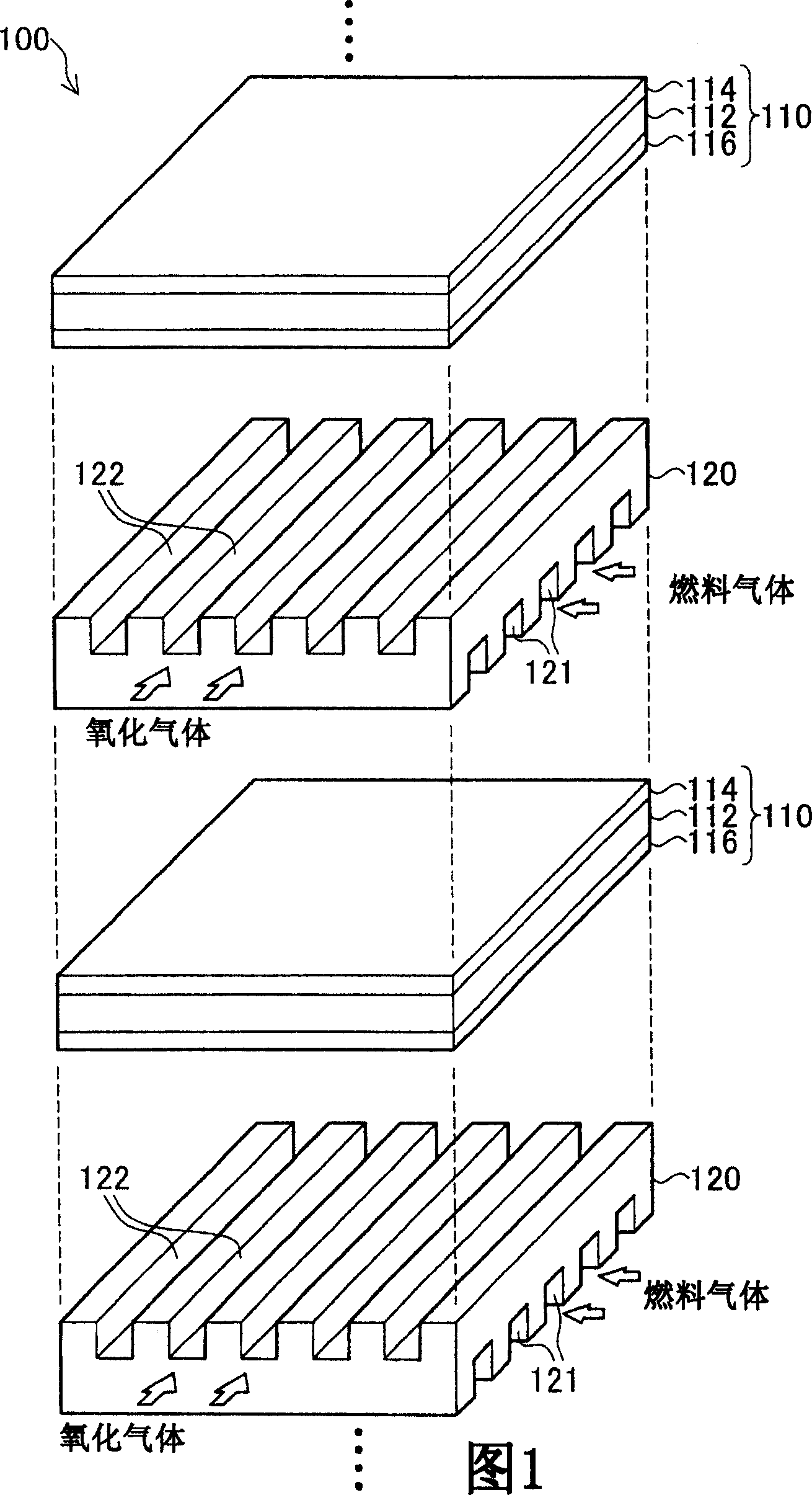
The cathode 114 is formed by forming several layers comprising an inorganic material that is primarily electron conductive and a complex oxide B that is primarily oxygen ion conductive and that supports an oxygen dissociation-promoting catalyst, on an electrolytic membrane 112. The electrolytic membrane 112 and the outermost layer of the cathode 114 (layer of mixture furthest from the electrolytic membrane 112) facing the separator 120 are physically and electrically continuous by means of the inorganic material a and complex oxide B disposed between them.

Description

technical field [0001] The present invention relates to cathodes for use in fuel cells and methods for their manufacture. Background technique [0002] It is known that the cathode is an important factor in fuel cells that degrades the performance of the cell. A cathode reaction in a fuel cell using a proton conductor as an electrolyte is divided into the following three processes. [0003] (1): Oxygen decomposition and activation <chemistry num="001"> <chem file="200580012668_cml001.xml" / > < / chemistry> [0004] (2): Movement of oxygen ions <chemistry num="002"> <chem file="200580012668_cml002.xml" / > < / chemistry> [0005] (3): Formation of water <chemistry num="003"> <chem file="200580012668_cml003.xml" / > < / chemistry> [0006] (1) Oxygen separation activation is considered to be a rate-controlling step, and previous attempts have been made to increase the activity of (1) by enlarging the reaction field. ...

Claims


Application Information

Patent Timeline
Patent Type & Authority Applications(China)
IPC IPC(8): H01M4/02H01M4/92H01M4/86H01M4/88H01M4/94H01M8/02H01M8/10H01M8/12
CPCH01M4/923H01M2004/8689Y02E60/521H01M4/8885H01M4/8657Y02E60/50Y02E60/525H01M4/9066H01M4/94H01M2008/1293Y10T156/10
Inventor 伊藤直树近藤彰
Owner TOYOTA JIDOSHA KK
Learn More