CMOS of chip digital controlled complementary type LC oscillator in low noise

A complementary oscillator technology, applied in power oscillators, automatic power control, electrical components, etc., can solve problems such as high power consumption, increased chip manufacturing costs, and strong dependence

Inactive Publication Date: 2007-05-09
TSINGHUA UNIV
View PDF0 Cites 12 Cited by
  • Summary
  • Abstract
  • Description
  • Claims
  • Application Information

AI Technical Summary

Problems solved by technology

However, the common disadvantage of the above-mentioned oscillators is that their frequency adjustment accuracy, phase noise, and spurious performance are heavily dependent on the selected CMOS manufacturing process. Achieve relatively good performance, while Infineon's digitally controlled LC oscillator uses the most expensive 65nm process, which will greatly increase the cost of chip manufacturing
At the same time, in order to meet the stringent requirements of the wireless communication transceiver on the phase noise of the oscillator, the current digitally controlled LC o

Method used


Image

  • CMOS of chip digital controlled complementary type LC oscillator in low noise
  • CMOS of chip digital controlled complementary type LC oscillator in low noise
  • CMOS of chip digital controlled complementary type LC oscillator in low noise

Examples


Embodiment Construction

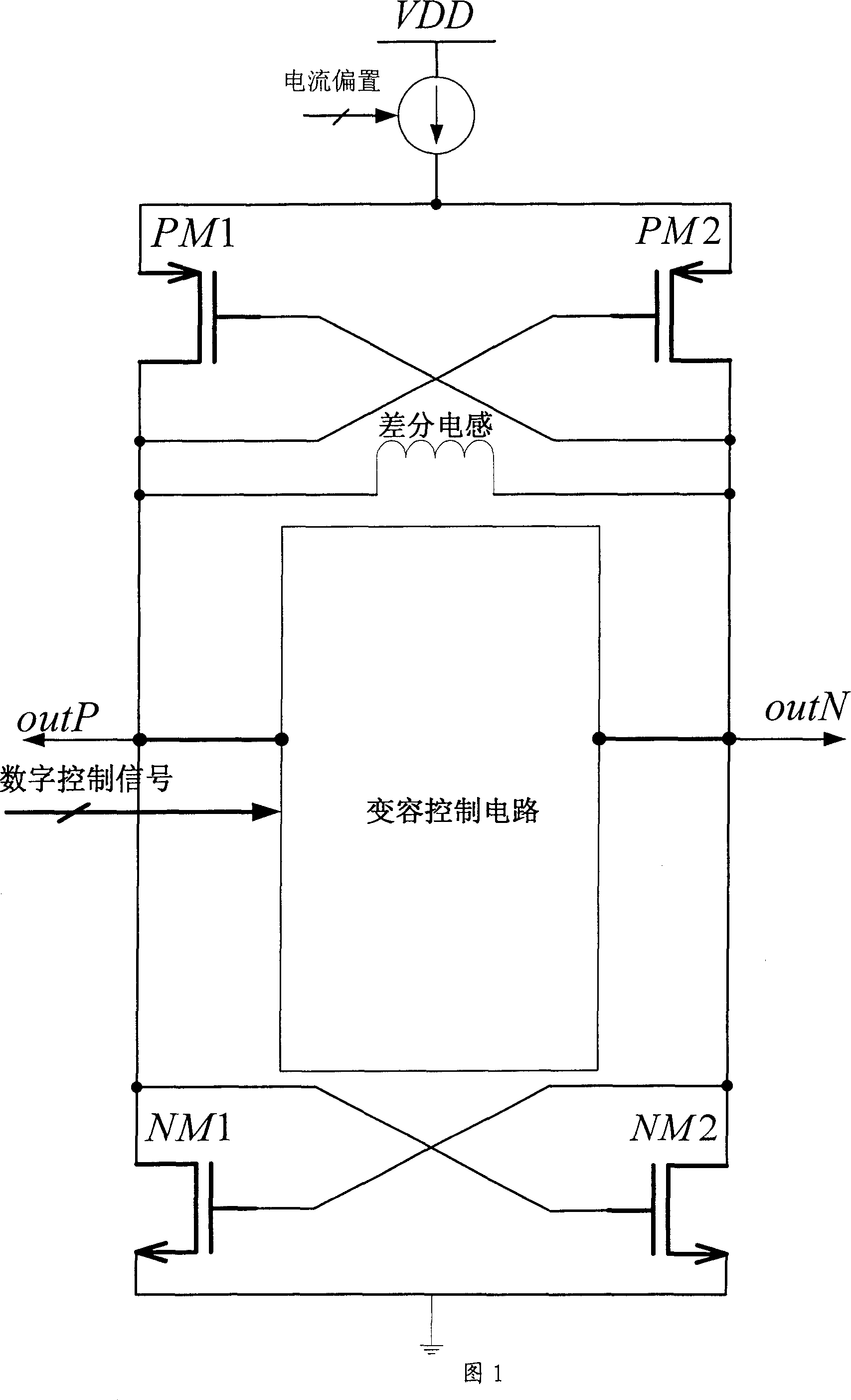
[0043] The technical solution of the present invention is: to improve the circuit structure of the commonly used voltage-controlled LC oscillator, and discretely control the capacitance value of the LC oscillation circuit by inputting a digital signal, so as to output a specified oscillation frequency. In the LC oscillation circuit, the oscillation frequency is determined by the following formula:

[0044] f out = 1 2 π LC , - - - ( 1 )

[0045] where f out is the oscillation frequency of the LC oscillation circuit, L is the loop inductance value, and C is the loop capacitance value. It can be seen from formula (1) that if the capacitance value in the oscillating circuit can be changed correspondingly according to the input digital signal, th...


PUM


Abstract

The special feature lay on that: adopts the novel digital control mutual complementary type MOS capacity-variable diode to build digital control oscillator, therefore reduces the phase noise and stray of the oscillator and raises the frequency modulation precision of the oscillator. Comparing with the existed method, the method raises the function of the CMOS on-chip oscillator effectively, reduces the oscillator power and benefits to reduce the receiver cost and power consumption.

Description

technical field [0001] The invention relates to a novel on-chip CMOS digital control complementary structure low-noise LC oscillator, which is especially suitable for the design of CMOS integrated chips for wireless communication system transceivers. Background technique [0002] The rapid development of the personal communication market requires that the personal handheld terminal of the communication system is increasingly developing in the direction of low cost, low power consumption, miniaturization, and support for multiple modes of operation. The only way to meet the above requirements is the integration of transceiver chips. Realize the so-called system on chip (SOC: System On Chip), that is, integrate the radio frequency, analog and digital modules of the transceiver on one chip as much as possible, and at the same time reduce the number of discrete components outside the chip as much as possible. With the continuous shrinking of CMOS integrated circuit process size,...

Claims


Application Information

Patent Timeline
IPC IPC(8): H03B5/12H03L7/099
Inventor 王少华杨华中
Owner TSINGHUA UNIV
Why Eureka
Try Eureka