Continuous carbonizing treatment method by internal heating self-combusting mode

A treatment method and carbonization technology, which can be used in combustion methods, rotary carbonization furnaces, incinerators, etc., and can solve problems such as rising fuel costs.

Inactive Publication Date: 2007-05-16
MAYEKAWA MFG CO LTD
View PDF0 Cites 21 Cited by
  • Summary
  • Abstract
  • Description
  • Claims
  • Application Information

AI Technical Summary

Problems solved by technology

However, in the proposed method, since the flame is blown into the inside of the rotary kiln from the downstream side of the rotary kiln, and the flame is continuously blown in during the process, there is a problem that the cost of the fuel increases significantly.
In addition, in this conventional method, it is almost impossible to efficiently carbonize treatment objects such as sewage sludge and food sludge with high moisture content, irregular shape, and high viscosity.

Method used


Image

  • Continuous carbonizing treatment method by internal heating self-combusting mode
  • Continuous carbonizing treatment method by internal heating self-combusting mode
  • Continuous carbonizing treatment method by internal heating self-combusting mode

Examples


Embodiment Construction

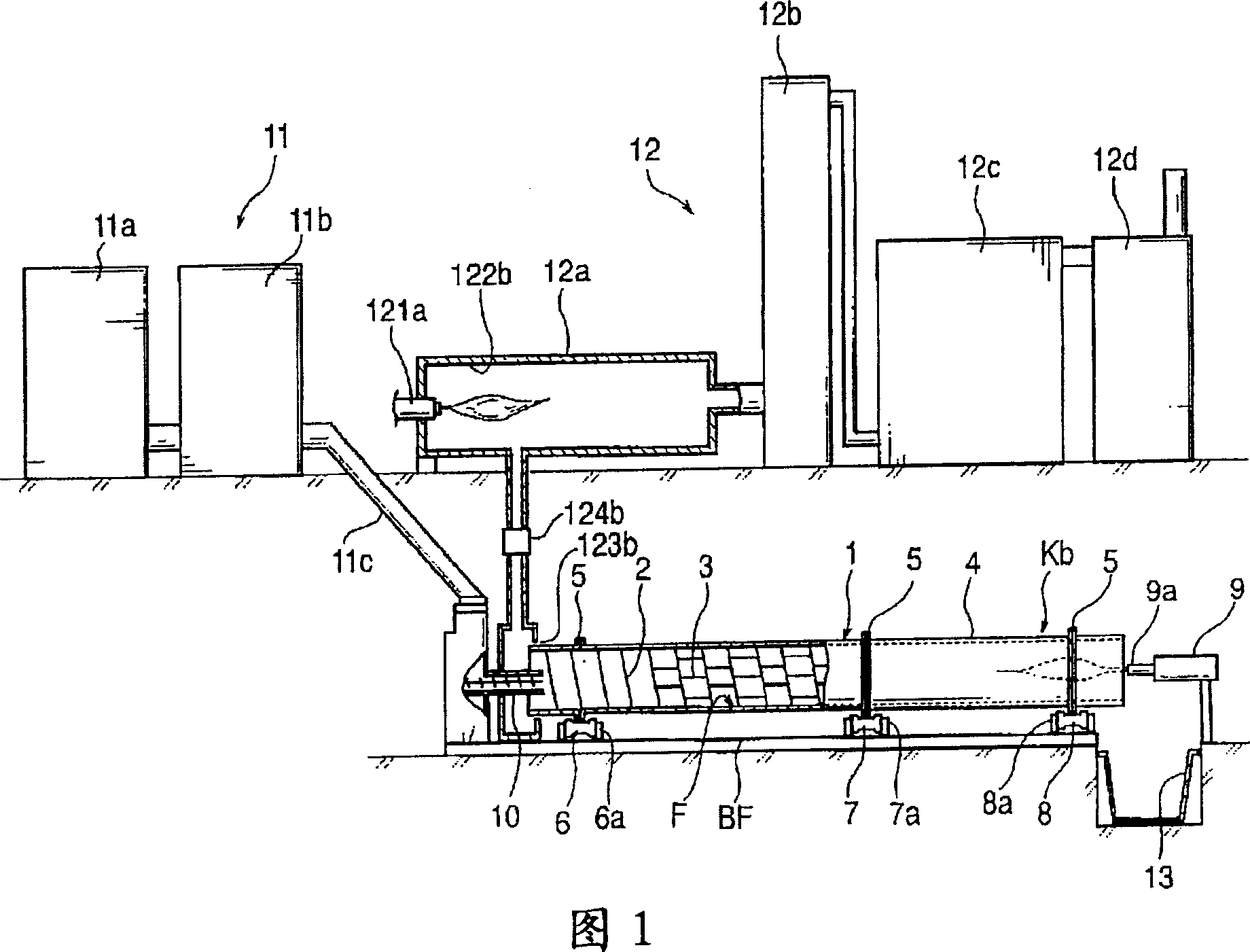
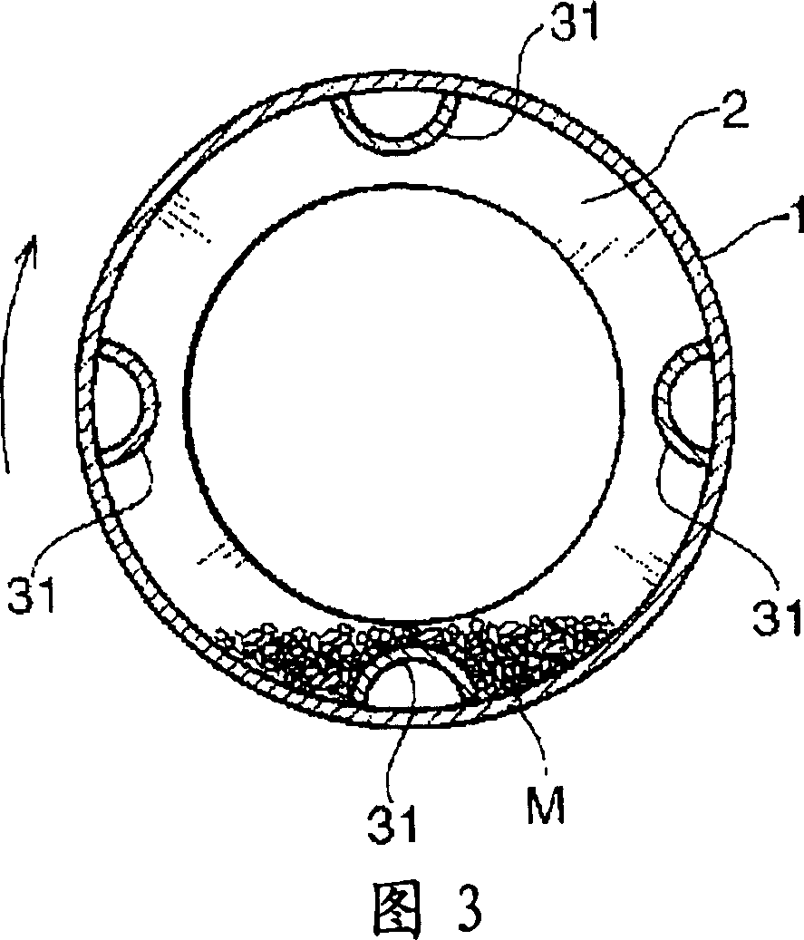
[0016] In FIG. 1 , 1 is a steel pipe cylinder having a length of about 10 to 15 m and an inner diameter of about 30 to 80 cm. Here, a plurality of required cylinders per unit length are connected by an outer flange-shaped joint, thereby forming one cylinder 1 .

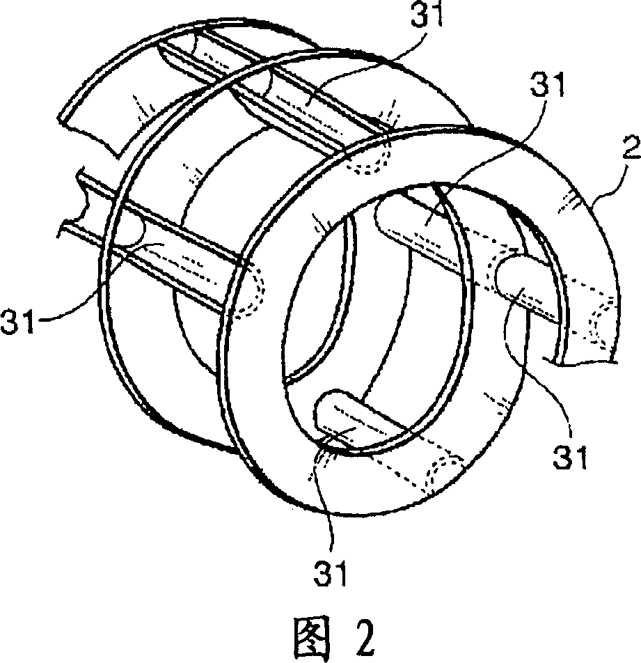
[0017] Reference numeral 2 denotes a conveying wall provided on the inner surface of the above-mentioned cylinder 1 so as to form a spiral over the entire length of the cylinder 1 . A stirring wall 3 having a substantially semicircular, substantially triangular, or substantially trapezoidal cross-section is provided on the portion from upstream to the middle of the spiral conveying wall 2 in a direction transverse to the conveying wall 2 of this portion.

[0018] Reference numeral 4 denotes a heat insulating layer provided outside the entire length of the above-mentioned cylindrical body 1 . The rotary kiln main body Kb is formed from the above-mentioned structure from the cylinder body 1 to the heat insulating layer...


PUM

PropertyMeasurementUnit
lengthaaaaaaaaaa

Abstract

The present invention provides a processing method which can process biomass resources to a carbide having a uniformity and including a large amount of high-carbon charcoal, can hold down an initial cost while capable of executing a large amount of process (for example, 100 ton per day), has a low running cost while can suppress a fuel consumption to a significantly low level, and can continuously carbonize a object having a high water content, having an unstable shape and having a high viscosity such as a sewage sludge even being a simple structure. The carbonization processing method has the steps of (i) continuously supplying a processing object M which is not preliminarily treated, or a processing object M which is formed at a predetermined magnitude by a preliminary treatment such as a fragmentation, a water content reduction or the like, from an upstream side of a cylindrical rotary kiln in which a spiral carrier wall is provided in an inner peripheral surface in an entire length and an agitating wall cutting across the carrier wall is formed in the carrier wall in a middle portion from the upstream side at a predetermined unit amount while rotating the rotary kiln, (ii) blowing a flame in an inner portion of the rotary kiln from a downstream side in a carrying direction of the rotary kiln in the state (i), and stopping the blowing of the flame if the processing object M is ignited within the rotary kiln, (iii) supplying an air necessary for burning a combustible gas generated from the processing object M to an inner portion of the rotary kiln from a downstream side, and self burning the combustible gas without supplying any fuel, (iv) sucking a gas generated in the inner portion of the rotary kiln from the upstream side of the rotary kiln so as to detoxify and discharge, and (v) discharging the carbide of the processing object M from an outlet in the downstream side of the rotary kiln so as to cool by executing the operations in the (i) to (iv).

Description

technical field [0001] The present invention relates to a method for carbonizing wastes called biological resources and other combustible wastes in a very energy-saving and continuous large amount by using a rotary kiln. [0002] Here, the biological resources refer to sugar resources, starch resources, forest resources, forest resources, agricultural resources, livestock resources, aquatic resources, industrial resources, and living resources (food waste, sewage sludge). Background technique [0003] In the continuous carbonization treatment, there are external heat dry distillation continuous carbonization method and internal heat direct combustion continuous carbonization method. [0004] The external heat dry distillation continuous carbonization method is divided into multiple stages, and generally consists of the following steps: using a conveying device inside a cylindrical tube, and heating the outside of the tube to evaporate water to dry and carbonize the object to...

Claims


Application Information

Patent Timeline
Patent Type & Authority Applications(China)
IPC IPC(8): C10B49/02C10B53/00C10B53/02F27B7/14F23G5/20F23G5/44C10B1/10C10B49/04
CPCC10B1/10C10B53/00C10B49/04Y02E50/14Y02E50/10
Inventor 前川哲志
Owner MAYEKAWA MFG CO LTD
Why Eureka
Try Eureka