Sintering aid composition, ceramic composition, ceramic, ceramic electronic component and manufacture of ceramic electronic component
A technology of ceramic composition and sintering aid, which is applied in the direction of chemical instruments and methods, ceramic layered products, layered products, etc. It can solve the problems of difficult ceramic substrate mixing, high melting point, and inability to greatly reduce the sintering temperature
- Summary
- Abstract
- Description
- Claims
- Application Information
AI Technical Summary
Problems solved by technology
Method used
Image
Examples
Embodiment 1
[0028] The composition of the ceramic sintering aid of Example 1 of the present invention will be described.
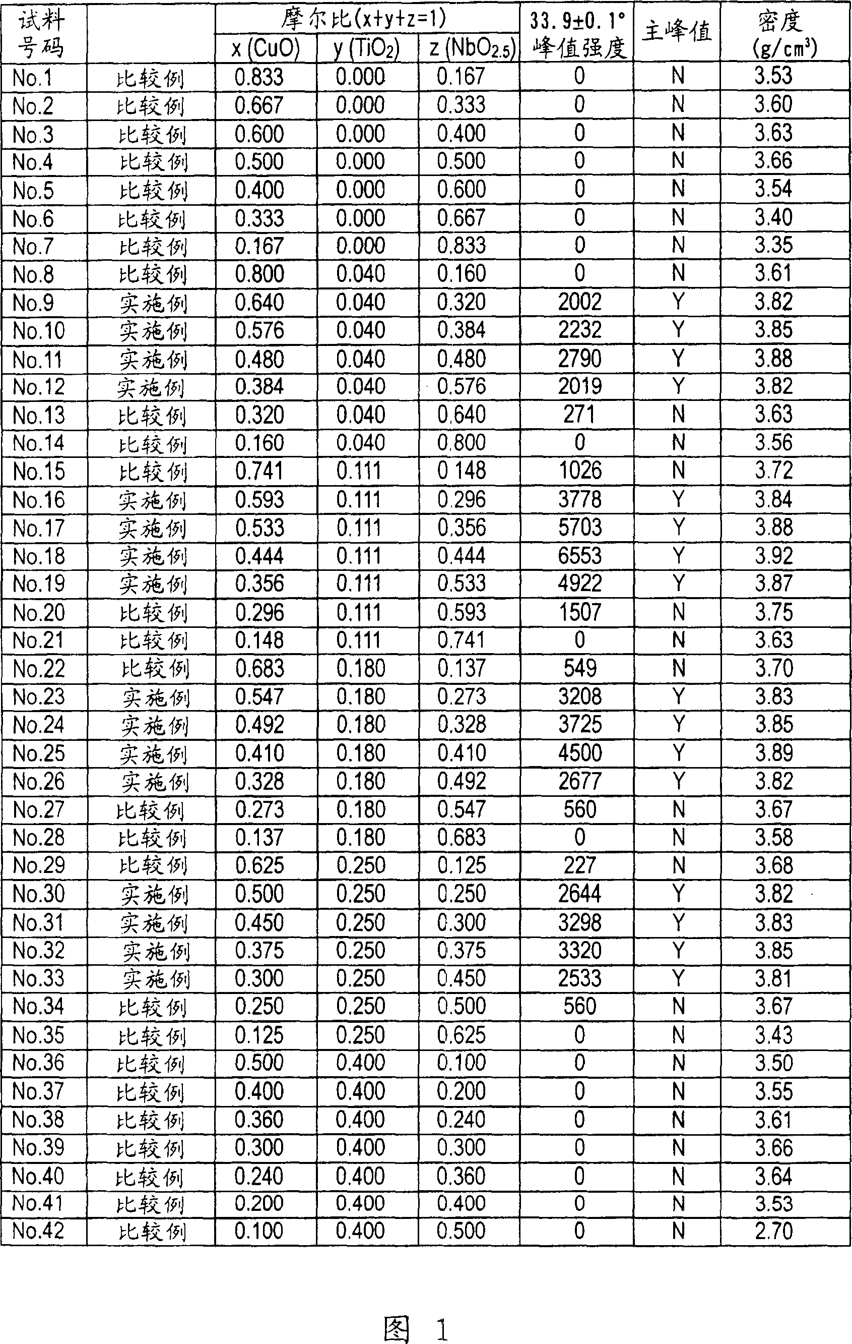
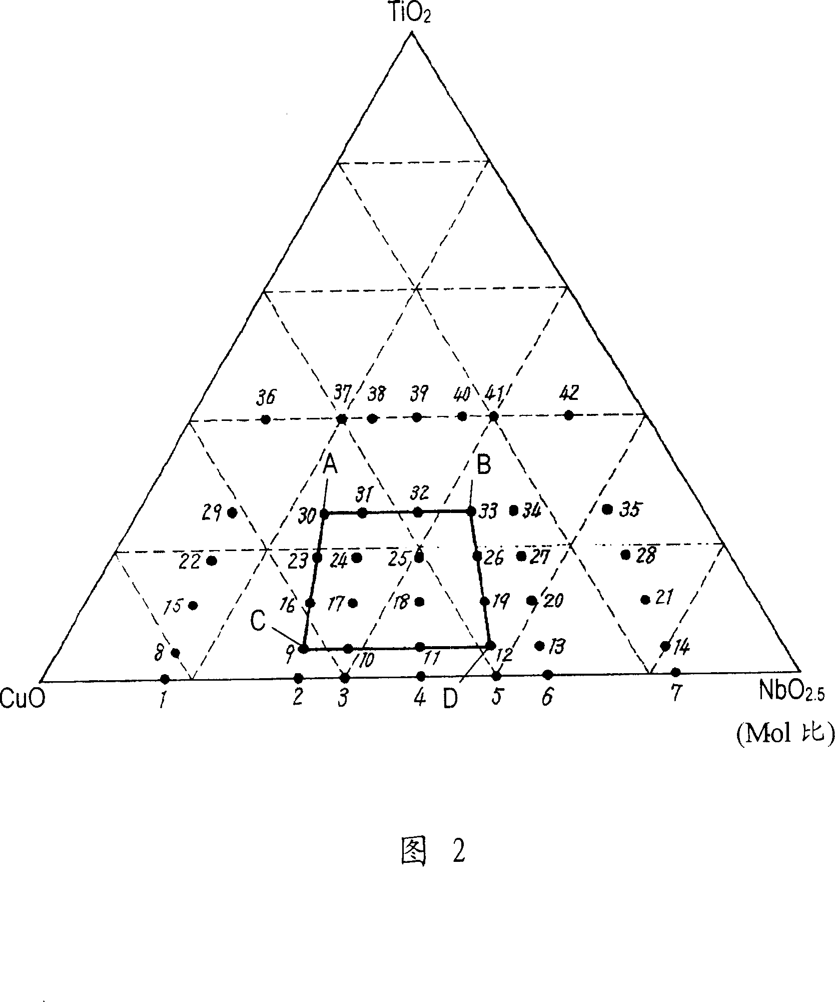
[0029] First, prepare copper oxide (CuO) and titanium oxide (TiO) with a purity of 99.99% and an average particle size of 0.1 to 5 μm 2 ), niobium oxide (Nb 2 o 5 ) powder. The above-mentioned three types of oxides were blended in the composition ratio shown in FIG. 1 to obtain samples of sample numbers No. 1 to 42. In Figure 1, the molar ratio of CuO is x, TiO 2 The molar ratio of is y. Nb 2 o 5 The molar ratio of NbO through 2.5 The conversion is z, where x+y+z=1.
[0030] 200% by weight of water was added to 100% by weight of the composition, and mixed for 24 hours with a ball mill using 5 mmφ zirconia. Thereafter, the mixed composition was sufficiently dried at 150° C. to obtain a powder of the composition of the sintering aid.
[0031] The obtained composition powder was held in air at a temperature increase rate of 300° C. / hr at a maximum temperature o...
Embodiment 2
[0076] 12A to 12C are cross-sectional views illustrating a method of manufacturing ceramic electronic component 1001 according to Example 2 of the present invention. FIG. 13 is a cross-sectional view of a ceramic electronic component 1001 prepared by the manufacturing method shown in FIGS. 12A to 12C .
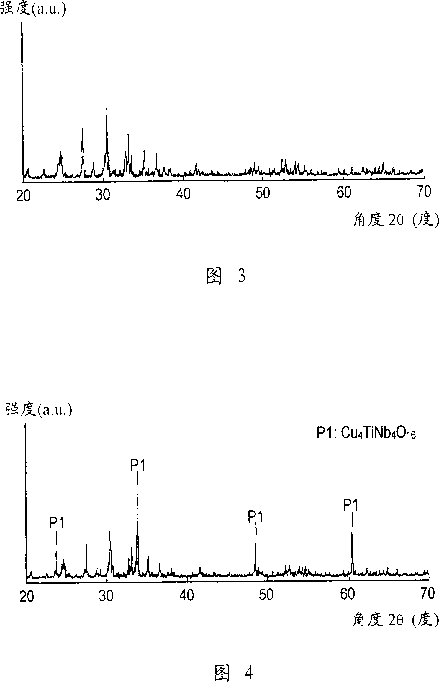
[0077] First, to a ceramic substrate composed of 100% by weight of alumina having an average particle diameter of 0.05 to 5 μm, 2.5 to 20% by weight of sample number No. 18 having an average particle diameter of 0.05 to 10 μm was added and sintered. Auxiliary composition for making ceramic composition. In addition, instead of the composition of the sintering aid, Cu 4 TiNb 4 o 16 The complex oxide phase of the sintering aid is uniformly distributed in the ceramic substrate.
[0078] Furthermore, 100% by weight of the ceramic composition was mixed with 50 to 300% by weight of water, and mixed with a dispersion medium using high-purity alumina of 1 to 5 mmφ by a ball mill fo...
Embodiment 3
[0092] FIG. 14 is a cross-sectional view of a ceramic electronic component 1002 in the third embodiment. Ceramic electronic component 1002 is different from ceramic electronic component 1001 of Example 2 shown in FIG. 13 in that ceramic layer 1001A having a higher dielectric constant than another ceramic composition 1001B is provided in multilayer substrate 901 . By arranging the electrode layers 803A facing each other on both surfaces of the ceramic layer 1001A, a high-capacity capacitor 1002A is formed in the multilayer substrate 901 . Therefore, it is possible to reduce the size and cost of the ceramic electronic component 1002 without the high-capacity capacitor component 903 shown in FIG. 13 .
[0093] The alumina-based ceramic green sheet 801 was formed with the composition of sample number No. 43 shown in FIG. 9 of Example 1, and the high dielectric constant ceramic layer 1001A was formed with the composition of sample number No. 48. .
[0094] The high dielectric con...
PUM
| Property | Measurement | Unit |
|---|---|---|
| density | aaaaa | aaaaa |
| particle size | aaaaa | aaaaa |
| particle size | aaaaa | aaaaa |
Abstract
Description
Claims
Application Information
 - R&D
- Intellectual Property
- Life Sciences
- Materials
- Tech Scout
- Unparalleled Data Quality
- Higher Quality Content
- 60% Fewer Hallucinations
Browse by: Latest US Patents, China's latest patents, Technical Efficacy Thesaurus, Application Domain, Technology Topic, Popular Technical Reports.
© 2025 PatSnap. All rights reserved.Legal|Privacy policy|Modern Slavery Act Transparency Statement|Sitemap|About US| Contact US: help@patsnap.com


