

Air supply device and system of engine
An engine and air-saving technology, applied in the direction of machine/engine, etc., can solve the problems of high cost, low conversion efficiency, and inability to dynamically adjust the air-fuel ratio, so as to reduce emissions, ensure stability, and reduce fuel consumption.
- Summary
- Abstract
- Description
- Claims
- Application Information
AI Technical Summary
Problems solved by technology
Method used
Image

Examples
Embodiment Construction
[0015] The realization principle of the present invention is to control the flow rate of the air supply by using the different openings of the throttle valve to reflect the load conditions of the engine through the linkage relationship between the air supply device and the throttle valve in the carburetor, and between the air supply device The amount of supplementary air to the engine is controlled by changing the area through which the airflow passes.
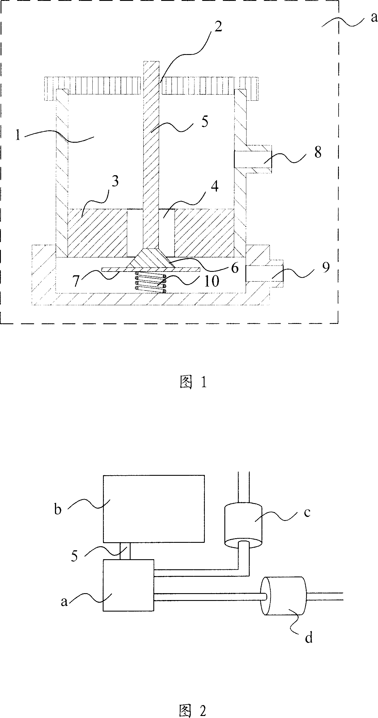
[0016] As shown in Figure 1, it is a schematic cross-sectional structure diagram of the engine air supply device of the present invention. The air supply device a is composed of the following components, including an air chamber 1, a communication hole 2, a throttle ring 3, a main metering hole 4, and a linkage rod 5 , Tapered oil needle 6, choke plate 7, air inlet 8 and air outlet 9. The function of the air chamber 1 is to accommodate air; the upper part of the air chamber 1 has a through hole as the communication hole 2, and...
PUM
 Abstract
Description
Claims
Application Information