Aqueous oxyhydrogen gas generator for use in IC engine

A generation device, a technology of hydrogen and oxygen, applied to internal combustion piston engines, oil supply devices, combustion engines, etc., can solve problems such as air pollution, car body hypoxia, suffocation and death, and achieve the effect of increasing mobility and solving hypoxia problems

Active Publication Date: 2007-07-11
白玉林
View PDF0 Cites 5 Cited by
  • Summary
  • Abstract
  • Description
  • Claims
  • Application Information

AI Technical Summary

Problems solved by technology

According to statistics at home and abroad, more than 75% of the environmental pollution in urban areas comes from motor vehicles, and the generation of exhaust gas from internal combustion engines and motor vehicles depends on the nature of the fuel used by internal combustion engines. At this stage, most internal combustion engine fuels are liquid gasoline and diesel oil. The official scientific names of its main components are C5--C12 alkanes and C15--C18 alkanes. When they burn, the flame is not stable and thorough, and the exhaust gas contains high levels of carbon monoxide, hydrocarbons, and nitrogen oxides. , causing severe air pollution
[0003] However, due to the increase of internal combustion engines, it has brought two major hazards that are difficult to solve so far. One is that the exhaust gas of internal combustion engines seriously pollutes the living environment on which human beings depend for survival; , is the driver and passengers, dizziness, brain swelling, nausea and vomiting and other symptoms, severe cases may cause suffocation death
[0004] In response to the above two major problems that have attracted the attention of the world, some countries have also taken corresponding measures to reduce the exhaust emissions of diesel locomotives. However, these two fatal problems have not been fundamentally solved so far.

Method used


Image

  • Aqueous oxyhydrogen gas generator for use in IC engine
  • Aqueous oxyhydrogen gas generator for use in IC engine
  • Aqueous oxyhydrogen gas generator for use in IC engine

Examples


Embodiment Construction

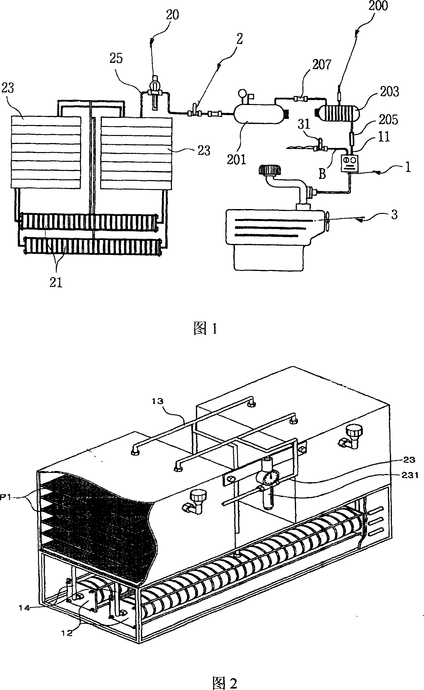
[0018] As shown in Figure 1, the water agent oxyhydrogen gas generating device that this internal combustion engine is used comprises the water agent oxyhydrogen gas separation tank 21 and the water reservoir 23, the gas storage buffer tank 201, One-way valve buffer tank 203, internal combustion combustion chamber 3, wherein the water reservoir 23 communicates with the water agent hydrogen-oxygen gas separation tank 21 through the liquid inlet pipe, and the water agent hydrogen-oxygen gas separation tank 21 communicates with the gas storage buffer tank through the hydrogen gas outlet pipe 25 201 is connected, the gas storage buffer tank 201 is connected to the one-way valve buffer tank 203 through the gas pipeline, the one-way valve buffer tank 203 is connected to the gas distribution valve 11 through the gas transmission pipeline, and the hydrocarbon input pipe B is also connected to the gas distribution valve In 11, the gas distribution output port 1 of the gas distribution v...


PUM


Abstract

The invention relates to a water agent oxy-hydrogen generating device in internal combustion engine, comprising water agent oxy-hydrogen generating device, shell of oxy-hydrogen machine and automatic control system. Separating tank for water agent oxy-hydrogen is set in the water agent oxy-hydrogen generating device and gas-liquid separating box is set on the shell of oxy-hydrogen machine. It is characterized in that water container set in the water agent oxy-hydrogen generating device is connected with the separating box of water agent oxy-hydrogen by liquid inlet pipe and the separating box of water agent oxy-hydrogen is connected buffering tank with one-way valve by air transporting pipe. The buffering tank with one-way valve is connected with air mixing valve by air transporting pipe. The transporting pipe for hydrocarbon is connected to the air mixing valve and the outlet port of air mixing valve is connected with the combustor of internal combustion machine. In the invention after fresh water, as raw material, is electrified, hydrogen and oxygen are distilled respectively. The hydrogen enters into the engine to burn and the oxygen enters into cab so as to solve the lack of oxygen when automobile is closed for a long time.

Description

technical field [0001] The invention relates to a hydrogen-oxygen generating device, in particular to a water-based hydrogen-oxygen generating device for an internal combustion engine for preparing hydrogen-oxygen gas from an aqueous solution and co-combusting the internal-combustion engine fuel. Background technique [0002] As we all know, the environmental pollution caused by the exhaust gas of internal combustion engines has caused great harm to people's physical and mental health. According to statistics at home and abroad, more than 75% of the environmental pollution in urban areas comes from motor vehicles, and the generation of exhaust gas from internal combustion engines and motor vehicles depends on the nature of the fuel used by internal combustion engines. At this stage, most internal combustion engine fuels are liquid gasoline and diesel oil. The official scientific names of its main components are C5--C12 alkanes and C15--C18 alkanes. When they burn, the flame ...

Claims


Application Information

Patent Timeline
Patent Type & Authority Applications(China)
IPC IPC(8): F02M21/02C25B1/04
CPCY02T10/32Y02E60/366Y02E60/36Y02T10/30
Inventor 白玉林
Owner 白玉林
Why Eureka
Try Eureka