
Coatings for controlling erosion of a substrate of an implantable medical device

a technology coatings, which is applied in the field of implantable medical devices, can solve the problems of high risk, increased risk of atherosclerotic plaque thrombosis, and significant mortality associated with vascular plaques, and achieve the effect of reducing, inhibiting or delay the erosion of the substrate region and preventing the thrombosis of atherosclerotic plaques

Inactive Publication Date: 2018-07-24
ABBOTT CARDIOVASCULAR
View PDF432 Cites 3 Cited by
  • Summary
  • Abstract
  • Description
  • Claims
  • Application Information

AI Technical Summary

Benefits of technology

The present invention relates to an implantable medical device with a bioabsorbable coating region that can control the erosion of the substrate region. The coating region can be made of a bioabsorbable polymer and a nonbioactive pore forming agent dispersed or mixed within the bioabsorbable polymer. The method for forming the coating region can control the thickness or degree of crystallinity of the coating region to allow for a specified amount of erosion of the substrate region during a selected time period. This invention can provide an implantable medical device with a controlled and regulated erosion rate for better safety and efficacy.

Problems solved by technology

While treatments of plaque-induced stenosis and restenosis have advanced significantly over the last few decades, the morbidity and mortality associated with vascular plaques have remained significant.
Unfortunately, as plaque matures, narrowing of a blood vessel by a proliferation of smooth muscle cells, matrix synthesis, and lipid accumulation may result in formation of a plaque which is quite different than a standard stenotic plaque.
Such atherosclerotic plaque becomes thrombosis-prone, and can be highly dangerous.
However, some erodible metals degrade much faster than a desired treatment time.
In addition, if a stent erodes too quickly, large pieces of the stent may detach from the eroding stent and cause embolization in a vessel.
In addition, polymers that exhibit a high degree of bulk eroding behavior can experience a substantial deterioration in mechanical properties that could lead to failure prior to the end of the treatment period.

Method used


Image

  • Coatings for controlling erosion of a substrate of an implantable medical device
  • Coatings for controlling erosion of a substrate of an implantable medical device
  • Coatings for controlling erosion of a substrate of an implantable medical device

Examples


Embodiment Construction

[0026]The term “implantable medical device” is intended to include, but is not limited to, self-expandable stents, balloon-expandable stents, stent-grafts, grafts (e.g., aortic grafts), artificial heart valves, cerebrospinal fluid shunts, pacemaker electrodes, and endocardial leads (e.g., FINELINE and ENDOTAK, available from Guidant Corporation, Santa Clara, Calif.). The structural pattern of the device can be of virtually any design.

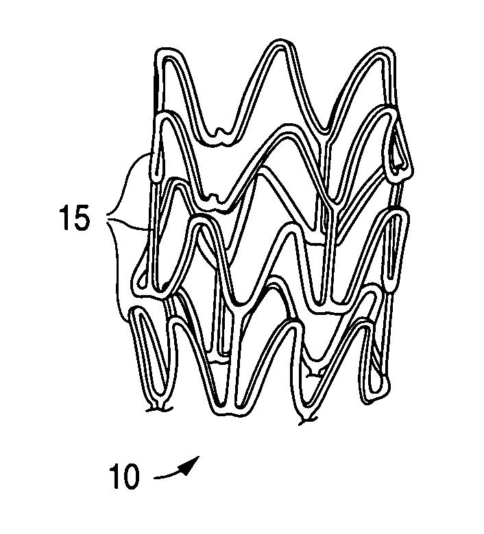
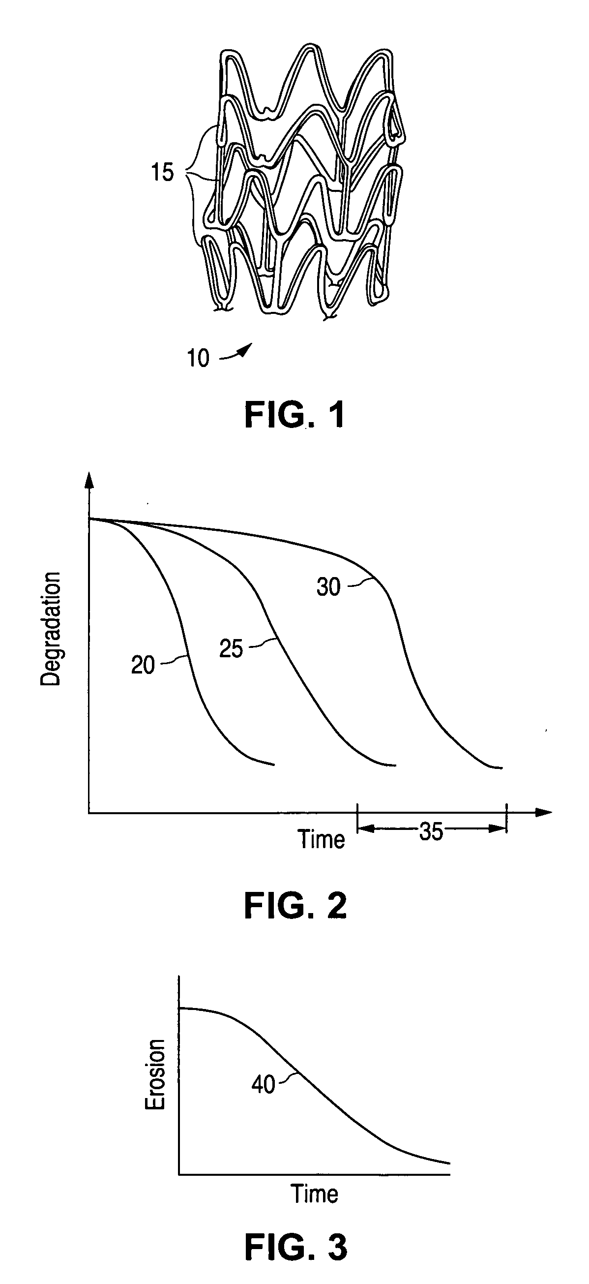
[0027]A stent, for example, may include a pattern or network of interconnecting structural elements or struts. FIG. 1 depicts a three-dimensional view of a stent 10 which shows struts 15. The pattern shown in FIG. 1 should not be limited to what has been illustrated as other stent patterns are easily applicable with the method of the invention. A stent such as stent 10 may be fabricated from a tube by forming a pattern with a technique such as laser cutting or chemical etching.

[0028]Various embodiments of the present invention relate to biodegradable im...


PUM

PropertyMeasurementUnit
diameteraaaaaaaaaa
bioabsorbableaaaaaaaaaa
erosion rateaaaaaaaaaa

Abstract

An implantable medical device, such as a stent, with a coating region for controlling erosion of the substrate region is disclosed.

Description

CROSS-REFERENCE[0001]This is a continuation-in-part of application Ser. No. 10 / 880,025 filed on Jun. 28, 2004, now U.S. Pat. No. 8,172,897, which is a continuation-in-part of application Ser. No. 10 / 767,296 filed on Jan. 28, 2004, now U.S. Pat. No. 7,699,890, which is a divisional application of application Ser. No. 10 / 235,033, which was filed on Sep. 3, 2002, and issued on Apr. 20, 2004, as U.S. Pat. No. 6,723,120 which is a continuation of application Ser. No. 09 / 797,313, filed on Mar. 1, 2001, abandoned on Oct. 11, 2002, which is a division of application Ser. No. 08 / 837,993, filed on Apr. 15, 1997, and issued Jun. 5, 2001 as U.S. Pat. No. 6,240,616.BACKGROUND OF THE INVENTION[0002]Field of the Invention[0003]This invention relates to implantable medical devices, such as stents, that have coatings that control erosion of bioabsorbable substrates of the devices.[0004]Description of the State of the Art[0005]This invention relates generally to implantable medical devices having a r...

Claims


Application Information

Patent Timeline
Patent Type & Authority Patents(United States)
IPC IPC(8): A61F2/06A61F2/915A61L31/14A61L31/10A61F2/91A61F2/00A61F2/90
CPCA61F2/915A61F2/91A61L31/10A61L31/146A61L31/148A61F2250/0019A61F2002/91533A61F2230/0013A61F2250/003
Inventor DUGAN, STEVEGALE, DAVID C.
Owner ABBOTT CARDIOVASCULAR
Learn More