Encapsulated quantum dots in porous particles

a quantum dots and porous particle technology, applied in the field of particles, can solve the problems of affecting the quality of light, affecting the effect of light intensity, and affecting the effect of light intensity, and achieve the effect of high efficacy and high quality white ligh

Active Publication Date: 2018-07-24
LUMILEDS
View PDF31 Cites 6 Cited by
  • Summary
  • Abstract
  • Description
  • Claims
  • Application Information

AI Technical Summary

Benefits of technology

[0004]Nanoparticles such as quantum dots (QDs) can possess properties which make them advanced luminescent materials to be used in solid state lighting. Here below, nanoparticles, such as quantum dots, that have the ability to give (visible) luminescence are also indicated as “light converter nanoparticles” or “luminescent nanoparticles”. They can e.g. be used in converting blue light to other colors, for obtaining high quality white light with high efficacy. Nanoparticles such as QDs have the advantage of a narrow emission band and color tunablility by varying the size of the particles.
[0005]Quantum Dots (QDs) are seen as a promising phosphor for LED applications. The narrow emission band (about 25-50 nm) and high quantum efficiency (QE) (>90% at 100° C.) makes them superior phosphors especially in the red, where alternative inorganic and organic phosphors show a much broader emission band. An overall improvement up to 20% in efficacy is expected in case QDs can be used as red phosphor in LEDs for general lighting applications. For backlight application the gain in efficacy can be even more, because the narrow band emission of both green and red QDs can be matched with the band pass filter of the LCD. All in all, QDs are envisaged to be an important green and / or red phosphor for LED applications in the near future.

Problems solved by technology

A major problem of QDs towards application is their sensitivity towards oxygen and water.
For example, the non-spherical shape and large size distribution which is obtained upon micro milling will hamper proper mixing of micro particles into a second host, and hinder hermetic encapsulation by a secondary coating.
Another disadvantage of micro beads in general is the mismatch in thermal expansion coefficient between QD-host material (typically an acrylate, silicone, or other polymer) and the encapsulation material (preferably an inorganic material such as alumina or silica).
A too large mismatch between thermal expansions may cause e.g. cracks.
It was found that when using organic micro beads, which are known from the prior art, such micro beads, even when these are substantially spherical, can hardly be coated with an inorganic coating, which is a preferred coating, without substantial mismatch in thermal expansion.
This may lead to life time reduction.
An irregular shape such as obtained by micro milling increases the chance of crack-formation even further in case of a large CTE mismatch.

Method used


Image

  • Encapsulated quantum dots in porous particles
  • Encapsulated quantum dots in porous particles
  • Encapsulated quantum dots in porous particles

Examples


example 1 preparation

of Impregnated Particles

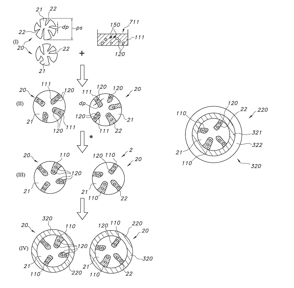
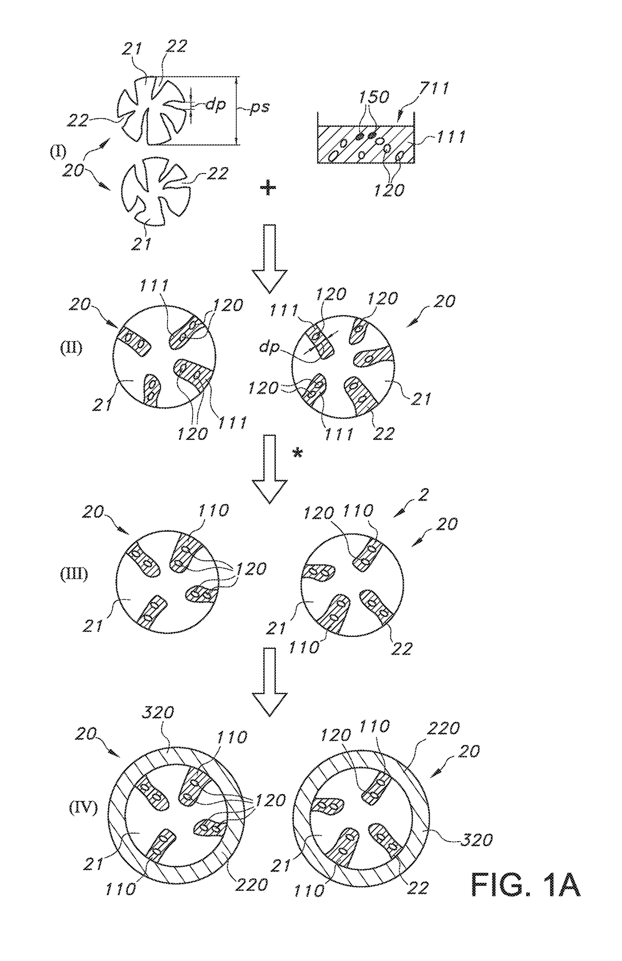
[0193]Trisoperl particles were impregnated according as follows: 1 gram of 5% wt dispersion of Crystalplex QDs in heptanes was added to IBMA / HDDA (5 g). This results in a 1% wt dispersion QDs in IBMA / HDDA, to which 1 gram of PSPs were added, and 0.5% wt photoinitiator (irgacure 184). The powder-acrylate mixture was put on a Buchner funnel, and filtrated for a few minutes in the glovebox. After filtration the powder was cured for 4 minutes with UV light in the glovebox. This results in a sticky powder, which was converted into a loose powder of individual PSPs by dispersing it in toluene and giving it a 15 minute US treatment in a close vial, hence no contact with ambient air. Next, the toluene was removed in the glovebox, by decanting, followed by evacuation of a few hours to remove all toluene. FTIR measurements show that the acrylic has a 95% conversion rate, which means a nearly complete curing of the acrylate. A subset of these particles was mixed into eb...

example 2 plasma

Enhanced ALD on Impregnated PSP

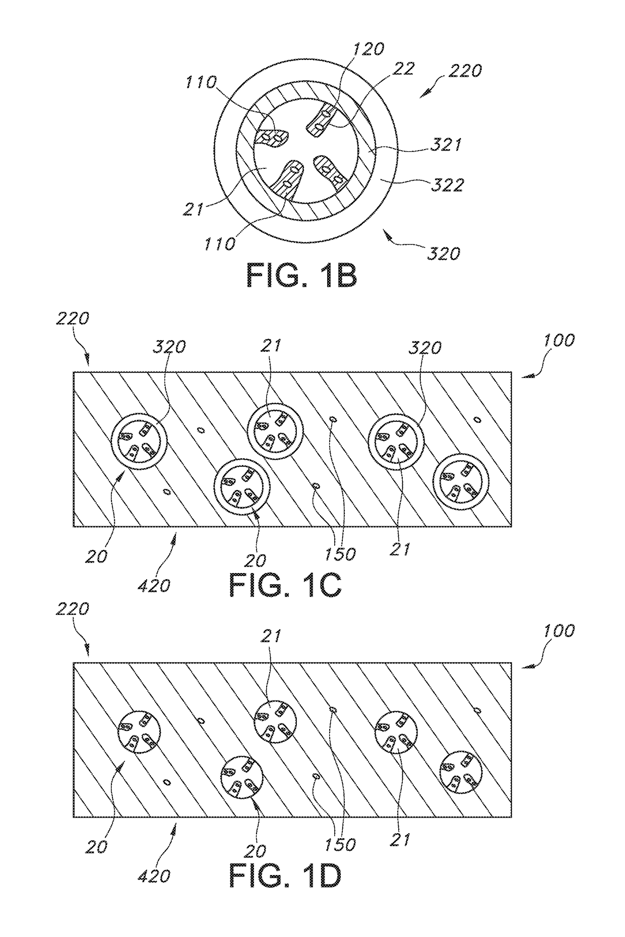
[0194]50 mg of the impregnated PSP (batch 1) was spread out over a silicon wafer (outside the glovebox), and inserted into the Emerald chamber (for plasma enhanced ALD) of an ASM dual chamber ALD system. A 50 nm alumina layer was applied using the plasma-enhanced ALD process at 100 C, using TMA (trimethylaluminium) and O2 as reactive gasses. After deposition, the powder was harvested and mixed into Ebecryl 150 (with 1% wt irgacure 184) to make cured films of the ALD-coated PSP's in a secondary matrix. As described above in example 1, reference samples of the same impregnated PSP's without ALD were also made, in addition to films of plain QDs in IBMA / HDDA (no impregnation). In all cases, the samples consisted of a 100 um acrylic layer, in between two glass plates. The QE of the ALD-coated PSP's using plasma enhanced ALD (called sample ALD-a from here on) had a QE of 50%, which is the same as before ALD coating (batch 1, 52%). The ALD coating thus has (a...

example 3

Thermal ALD@150 C on Impregnated PSP

[0204]30 mg of the impregnated PSP (batch 1) was spread out over a silicon wafer (outside the glovebox), and inserted into the Pulsar chamber (for thermal ALD) of an ASM dual chamber ALD system. A 50 nm alumina layer was applied using the thermal ALD process at 150 C, using TMA (trimethylaluminium) and O3 as reactive gasses. After deposition, the powder was harvested and mixed into Ebecryl 150 (with 1% wt irgacure 184) to make cured films of the ALD-coated PSP's in a secondary matrix. The QE of the ALD-coated PSP's using thermal ALD at 150° C. (called sample ALD-b from here on) had a QE of 31%, which is a drop of 20% compared to before ALD coating (batch 1, QE of 52%).

[0205]A small part of the thermal ALD coated particles from ALD-b was used to make cross-sections and investigate in SEM. FIG. 7a shows a SEM image of PSP's with ALD-b coating. In the prepared Schliffs (cross-sections) some of the particles were not fully embedded in the epoxy carrie...


PUM

PropertyMeasurementUnit
particle sizesaaaaaaaaaa
pore sizesaaaaaaaaaa
QEaaaaaaaaaa

Abstract

The invention provides a process for the production of a (particulate) luminescent material comprising particles, especially substantially spherical particles, having a porous inorganic material core with pores, especially macro pores, which are at least partly filled with a polymeric material with luminescent quantum dots embedded therein, wherein the process comprises (i) impregnating the particles of a particulate porous inorganic material with pores with a first liquid (“ink”) comprising the luminescent quantum dots and a curable or polymerizable precursor of the polymeric material, to provide pores that are at least partly filled with said luminescent quantum dots and curable or polymerizable precursor; and (ii) curing or polymerizing the curable or polymerizable precursor within pores of the porous material, as well as a product obtainable thereby.

Description

CROSS-REFERENCE TO PRIOR APPLICATIONS[0001]This application is the U.S. National Phase application under 35 U.S.C. § 371 of International Application No. PCT / IB2014 / 059970, filed on Mar. 19, 2014, which claims the benefit of U.S. Patent Application No. 61 / 803,563, filed on Mar. 20, 2013, EP Patent Application No. EP14153775.3, filed on Feb. 4, 2014 and EP Patent Application No. EP14159373.1 filed on Mar. 13, 2014. These applications are hereby incorporated by reference herein.FIELD OF THE INVENTION[0002]The invention relates to a (particulate) luminescent material, as well as to a production process for such (particulate) luminescent material. The invention further relates to a wavelength converter and lighting device comprising such (particulate) luminescent material.BACKGROUND OF THE INVENTION[0003]Quantum dot (QD) based lighting is known in the art. WO2012021643, for instance, describes systems and methods that relate to quantum dot structures for lighting applications. In partic...

Claims


Application Information

Patent Timeline
Patent Type & Authority Patents(United States)
IPC IPC(8): F21K99/00C09K11/02F21V9/30B05D1/18C23C16/40C23C16/455F21K9/64F21Y115/10
CPCF21V9/30B05D1/18C09K11/02C23C16/403C23C16/45525F21K9/64C09K11/025F21Y2115/10C09K11/08F21V7/30F21V9/32
Inventor KOOLE, ROELOFBOHMER, MARCEL RENEKRIEGE, JAN CORNELISVERHOECKX, GODEFRIDUS JOHANNESOFFERMANS, PAULUS HUBERTUS GERARDUSBAESJOU, PATRICK JOHNKEUR, WILHELMUS CORNELISCILLESSEN, JOHANNES FRANCISCUS MARIAVERSTEGEN, EMILE JOHANNES KARELDE LAAT, ANTONIUS WILHELMUS MARIA
Owner LUMILEDS
Why Eureka
Try Eureka