Waveguide structures in anisotropic lasing and nonlinear optical media

Active Publication Date: 2018-07-24
ONYX OPTICS
View PDF19 Cites 6 Cited by
  • Summary
  • Abstract
  • Description
  • Claims
  • Application Information

AI Technical Summary

Benefits of technology

The patent text describes a method for making optical devices using a special crystal structure called a positive crystal. These devices can be made using a process called adhesive-free bonding, which ensures a strong and rigid bond between components. The technique works by reversing the polarization of the incoming beam of light to ensure that it matches the design of the crystal structure. This results in devices that operate in a single mode, and have good performance. Overall, the method allows for the fabrication of high-quality optical devices using standard techniques.

Problems solved by technology

From the above analysis, one can see that the ultimate energy limitation for a pulsed crystalline fiber laser will be mainly derived from the saturation fluence, laser damage and possibly the nonlinear effect.
However, since the thickness of the film left at the bonding interface is thick and uncontrollable, it is inappropriate for applications requiring precision thickness control.
Scattering loss can also occur in these optically thick interfaces.
Being organic material, epoxy is vulnerable to high-intensity optical powers or UV exposure.
Moreover, epoxy bonds are not particularly heat resistant or chemically robust.
The drawbacks include increased scattering loss in the final interface since channels have to be made to allow frit to flow between the parts.
The process results in 100% optically transparent optical paths with negligible scattering and absorptive losses at the interfaces, since the two surfaces are literally contacting each other without anything in between.
However, because the process is not very robust and optical contact can be easily broken, parts optically contacted in the traditional manner must be sealed around the edges to prevent breaking the contact.
This requirement renders further processing as described below exceedingly difficult if not impossible.
CADB suffers from drawbacks, such as a chemical bond interface of a layer that is different from the two components to be bonded, therefore having lower intrinsic strength.
There are hydroxyl groups remaining at the interface that cannot be removed by heat treatment, resulting in instability of the bond and continuing chemical reaction as function of time.
An unfortunate effect of this method is that injection of protons will decrease nonlinearity of the waveguide and subsequently decrease frequency conversion capability of the waveguide.
However, no single-mode analysis was made or anticipated.

Method used


Image

  • Waveguide structures in anisotropic lasing and nonlinear optical media
  • Waveguide structures in anisotropic lasing and nonlinear optical media
  • Waveguide structures in anisotropic lasing and nonlinear optical media

Examples


example 1

near Waveguide

[0154]An embodiment of the present invention is a lithium triborate LiB3O5 (LBO) waveguide. LBO is a biaxial optics crystal with a wide transparency range. In the preferred embodiment, a slightly off-axis LBO is used as cladding material to sandwich an on-axis LBO core.

[0155]The purpose of the waveguide is to achieve second-harmonic generation from a fundamental beam of 1070 nm to its second harmonic of 535 nm. The fundamental beam is polarized on the z-axis, while the second-harmonic beam is polarized on they-axis. Both beams propagate along the x-axis.

[0156]Technical advantages of using LBO include but are not limited to:[0157]1) The refractive index is slightly smaller than the core material, for both fundamental and second harmonic waves;[0158]2) Since they are the same material, the coefficients of thermal expansion are compatible, given that the core and the cladding LBO crystals only have a small angular deviation between them; and[0159]3) The refractive index i...

example 3

ser Waveguide

[0179]Consider a 40 μm thick planar laser waveguide employing Yb:YLF as core material, such as that in FIGS. 4A-4E, for the purpose of emitting at 1030 nm.

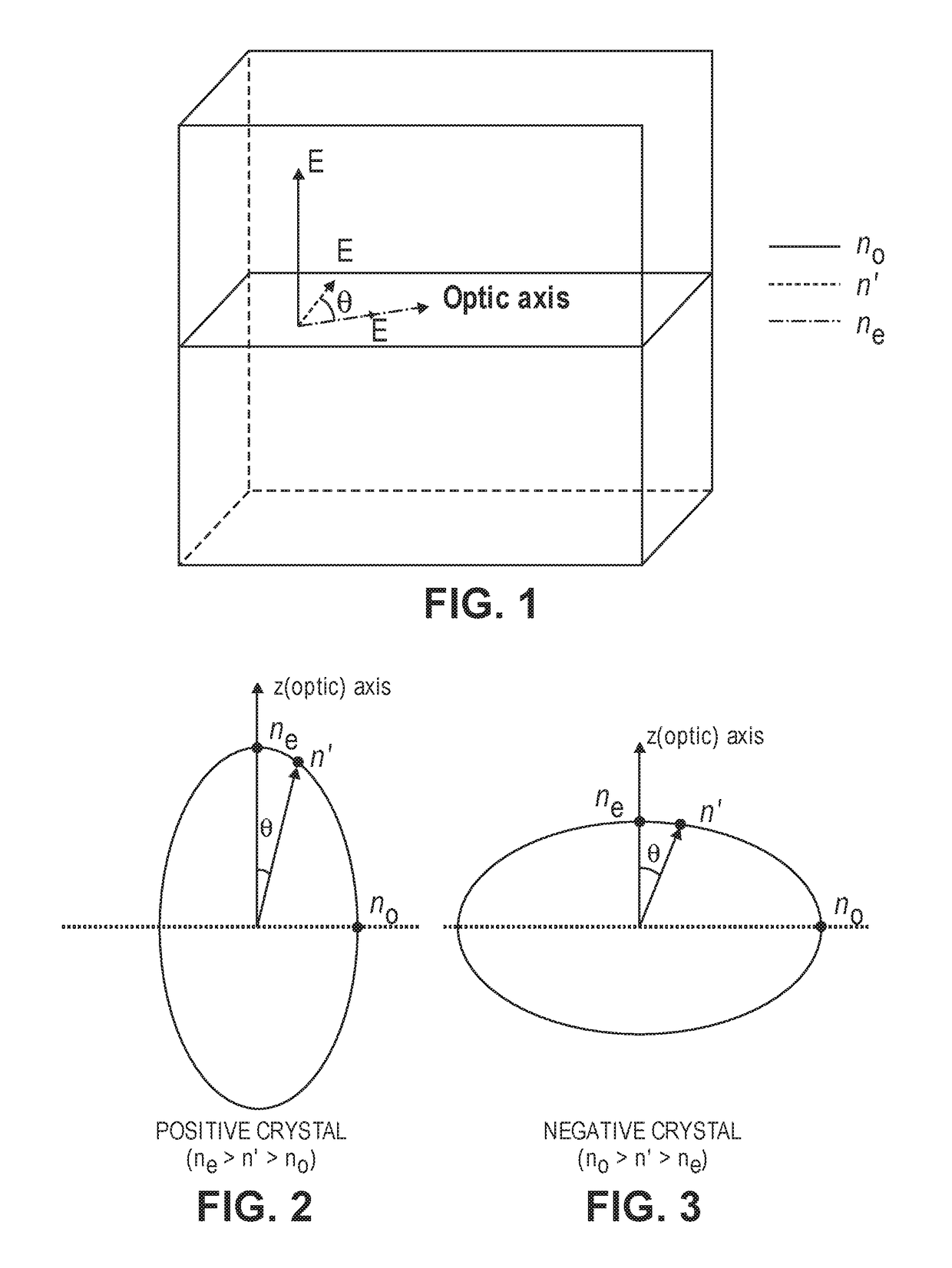
[0180]YLF is positive uniaxial crystal whose extraordinary refractive index ne=1.4704 and ordinary refractive index no=1.4482. For Yb:YLF laser, the emission line at 995 nm is polarized along the c-axis (extraordinary). Therefore, the inner cladding should be slightly tilted (see FIG. 4E) such that a single-mode waveguide along the lateral direction can be formed. According to Eq. (2), the index difference is calculated to be Δn=5.89×10⁻⁵. According to Eq. (5), tilt angle θ<0.051°. If single-mode operation is not a requirement, the tilting angle can be larger.

Example 4: Nd:YVO4 Laser Waveguide

[0181]A Nd:YVO4 waveguide is formed using a higher concentration Nd:YVO4 material as the core and lower concentration Nd:YVO4 material as the inner cladding. The refractive index difference needed to form a single-mode or multimo...

example 5

Waveguide Capped Yb:YLF Laser Waveguide

[0182]Consider an active gain medium of Yb:YLF, the same type as in Example 4. On the two ends, a short Nd:YLF waveguide, whose length is in the order of ˜5 mm, is bonded to the Yb:YLF waveguide. The absorption peak for Nd:YLF is at 808 nm, while the absorption peak for Yb:YLF is at 960 nm. When pumped at 960 nm, the two short Nd:YLF waveguides will not lase. The mode profile of the Nd:YLF waveguide is designed in such a way that it matches the mode profile of the Yb:YLF to the best extent by slightly tilting the inner cladding Nd:YLF, as described before, such that the laser radiation can propagate in the entire waveguide structure with minimal loss.

[0183]Technical advantages of such a capped laser waveguide design include: 1) protecting the optical coating; and 2) mitigating thermal-induced fracture, by moving the focus point of pump beam to the inactive end rather than directly focusing on the active gain medium.

[0184]Other Notes

[0185]A diff...


PUM


Abstract

A laser or nonlinear optical waveguide is presented that is formed from a core anisotropic crystal sandwiched by a cladding of anisotropic crystals of the same material but slightly rotated optical axes. The core and cladding crystals can be cut from the same crystal boule and bonded without adhesives between them. Because the crystals are anisotropic, the core and slightly skewed cladding crystals exhibit different refractive indexes to a propagating light beam. The difference in refractive indexes should be ≥1.2×10⁻⁶ for mode confinement and 2d / λ*Sqrt(ncore2−nclad2)≤1.37 to achieve single mode operation in a square cross section, ≤1 for a planar cross section. Alternative embodiments use slightly different doping amounts in crystals to achieve the difference in refractive indexes between the core and cladding.

Description

CROSS-REFERENCES TO RELATED APPLICATIONS[0001]This application claims the benefit of U.S. Provisional Application No. 62 / 350,132, filed Jun. 14, 2016, which is hereby incorporated by reference in its entirety for all purposes.STATEMENT AS TO RIGHTS TO INVENTIONS MADE UNDER FEDERALLY SPONSORED RESEARCH AND DEVELOPMENT[0002]Not ApplicableBACKGROUND1. Field of the Invention[0003]The present invention generally relates generally to optical waveguides for use as an active laser medium or for frequency-changing optics and methods of manufacturing the same.2. Description of the Related Art[0004]The present invention relates generally to optical waveguides, and more particularly to a method of designing and producing intrinsic single-mode waveguides preferably via an adhesive-free bonding technique, for either laser emission / amplification or frequency conversion. Any other technique for joining may be applicable as long as it does not interfere with the performance of the device.[0005]Gener...

Claims


Application Information

Patent Timeline
IPC IPC(8): G02B6/10G02F1/365H01S3/063G02F1/355H01S3/109G02B1/02
CPCG02F1/3551H01S3/0632G02F1/365H01S3/109G02B6/10G02B1/02H01S3/08045H01S3/1611H01S3/1618H01S3/1653
Inventor LI, DAMEISSNER, HELMUTH E.MEISSNER, STEPHANIE K.
Owner ONYX OPTICS
Why Eureka
Try Eureka